Ponchonutty
Full Access Member
Thought I would share an install done today on this truck below and give a little tips/tricks for those wanting to do this themselves. Mind you, this isn't for the faint of heart because it does involve drilling, cutting, and wiring into the vehicle.
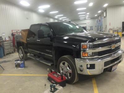
Here's the patient!
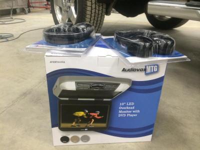
Here's the products being installed.
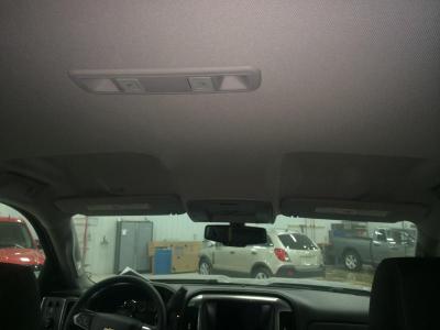
First deciding on the layout of the system. Since this was a large unit, I decided to mount it towards the rear so when open the screen isn't in the drivers face. This involved removing the OEM domelights.
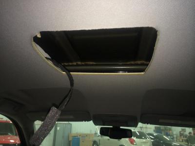
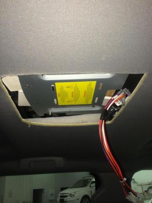
Used the DVD's mount as a template and cut open the headliner.
Splicing the DVD system's domelight into the vehicles wiring. DO NOT USE THIS CIRCUIT FOR ANY OTHER PART OF INSTALL SUCH AS DVD POWER.
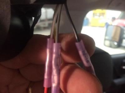
This is the only thing I do not like about this kit. It's the fuse and noise choke. The housing is HUGE so I cut it off and wrap it with tape so it's easier to hide in the headliner.
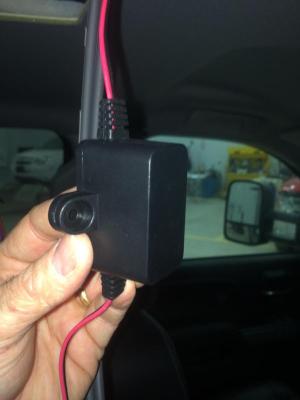
This is one of those $1 tools you just can't be without. It's actually a furnace zip tie. I cut the end off and drill small holes. Makes a nice fishtape and don't have to worry about poking through anything.
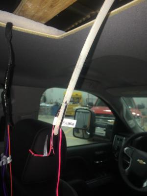
There's virtually nothing in the roof to attach to other than the brace the factory lights were which isn't enough for the screen. So, I epoxied a piece of 3/4" plywood for added strength
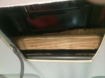
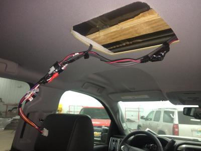
Plate installed
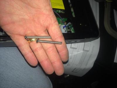
The kit comes with 3 different sizes of screws to mount the unit. I like to use the longest ones to just help line it up. I use 2 of them then go to the shortest ones I can get by with on the remaining 2 screw holes.
Running wire down pillar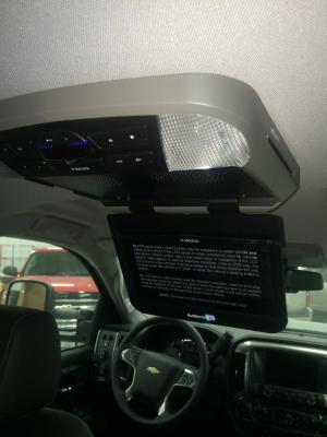
Running cables through existing channel
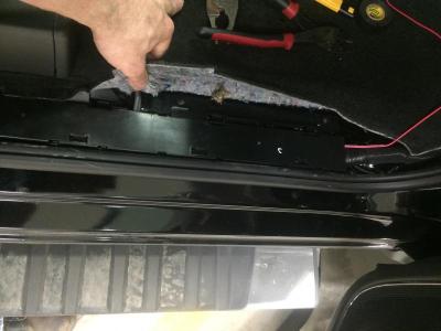
With the bottom console map pocket removed gives just enough room to run cables under the seat/carpet up into the console
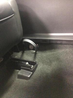
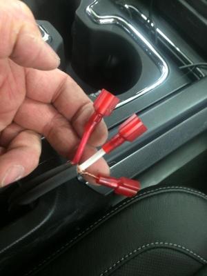
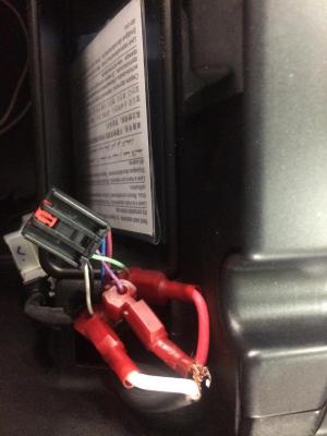
I cut the ends of the RCA's off and used 3m spades and 3m t-taps to patch into the audio input inside the console.
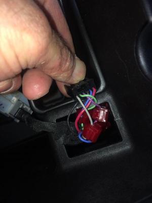
You will need to cut the BLUE wire in this harness so the radio thinks an item is connected to the unit. Without doing this step, you will not get audio into the radio.
For power I went into the driver's side fuse panel. There's a spade terminal open that's switched to the accessory. Sorry, no picture of that.
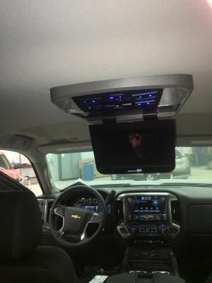
Finished project.
Here's the patient!

Here's the products being installed.

First deciding on the layout of the system. Since this was a large unit, I decided to mount it towards the rear so when open the screen isn't in the drivers face. This involved removing the OEM domelights.

Used the DVD's mount as a template and cut open the headliner.

Splicing the DVD system's domelight into the vehicles wiring. DO NOT USE THIS CIRCUIT FOR ANY OTHER PART OF INSTALL SUCH AS DVD POWER.

This is the only thing I do not like about this kit. It's the fuse and noise choke. The housing is HUGE so I cut it off and wrap it with tape so it's easier to hide in the headliner.

This is one of those $1 tools you just can't be without. It's actually a furnace zip tie. I cut the end off and drill small holes. Makes a nice fishtape and don't have to worry about poking through anything.

There's virtually nothing in the roof to attach to other than the brace the factory lights were which isn't enough for the screen. So, I epoxied a piece of 3/4" plywood for added strength


Plate installed

The kit comes with 3 different sizes of screws to mount the unit. I like to use the longest ones to just help line it up. I use 2 of them then go to the shortest ones I can get by with on the remaining 2 screw holes.

Running wire down pillar

Running cables through existing channel

With the bottom console map pocket removed gives just enough room to run cables under the seat/carpet up into the console

I cut the ends of the RCA's off and used 3m spades and 3m t-taps to patch into the audio input inside the console.

You will need to cut the BLUE wire in this harness so the radio thinks an item is connected to the unit. Without doing this step, you will not get audio into the radio.


For power I went into the driver's side fuse panel. There's a spade terminal open that's switched to the accessory. Sorry, no picture of that.
Finished project.

