Don't ever change a fuse to a bigger one. A fuse rating is designated based on the wire size it's protecting and if you're blowing a fuse you need to find out why or else add another source with another wire and it's own fuse. Otherwise you're going to melt a wire in some place that you can't see. But when you're changing out all the lights in a circuit with led you're actually lowering the total draw even there's more lights since LED's draw very little current so the fuse should not blow.Did you just splice into the rear cargo light? Did you change the fuse for that light to a bigger one to handle more amps?
You are using an out of date browser. It may not display this or other websites correctly.
You should upgrade or use an alternative browser.
You should upgrade or use an alternative browser.
Cargo Area Light Mod
- Thread starter dbbd1
- Start date
Disclaimer: Links on this page pointing to Amazon, eBay and other sites may include affiliate code. If you click them and make a purchase, we may earn a small commission.
dbbd1
Full Access Member
- Joined
- May 12, 2017
- Posts
- 924
- Reaction score
- 355
I spliced straight in since leds take a small fraction of the power. And all the dome/map lights are led, so technically I'm still running less power than what the system is designed to handle.
Did you just splice into the rear cargo light? Did you change the fuse for that light to a bigger one to handle more amps?
But he had incandescent bulbs to begin with, then switched to LED's, which lowered his amp draw. You already have LED's with an appropriate size fuse. I would start with the stock fuse size and see if it works.
MechEng813
Member
- Joined
- Jan 11, 2017
- Posts
- 73
- Reaction score
- 63
I know the diagram is there but I’m more of a pictures guy. Do you have more pics of how you wired it to the switch? And also doing this mod do you have to buy more wire if so what size? And do you connect them all together in the back part of the panel. Do you have pics of the back of the panel?
Sorry for the Qs but I just want to do this right
I have to pull the panel out to get pics of it wired up, and I'll sketch up how I wired in the switch.
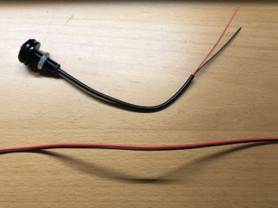
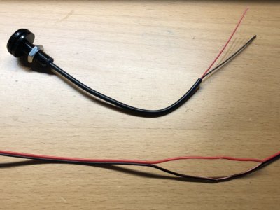
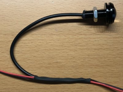
Here's how I wired each bulb in parallel.
(This was just a mock up bulb, so assume the bulb is in already in place on the panel with the nut holding it in)
1) Bought a length of this cable http://a.co/bmKDnws
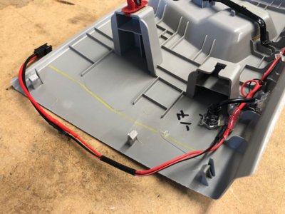
2) Laid it along the trim panel with all 4x of my LEDs mounted. (added this female socket to the end for future use http://a.co/cMJuoiA )
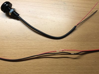
3) I separated segments at each light, using strippers exposed the bare wire offsetting the two sides about an inch apart.
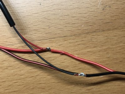
4) Stripped, then wrapped each wire, soldered the joint, then slid a long piece of shrink tube covering both offset joints. http://a.co/ffmyKWE
5) I did this one LED at a time, working my way down the line to minimize the amount of splices and solder work needed.
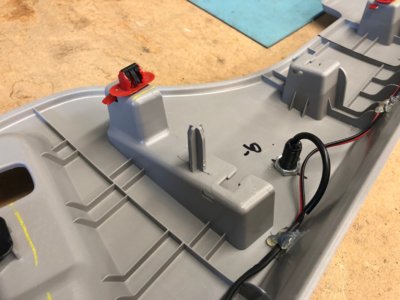
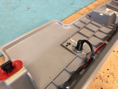
6) I used a hot glue gun to tack my wiring down onto the plastic trim to keep everything clean and inline.
7) Added a dab of glue on the threads and nut of each LED to act as a removable thread lock as well.
MechEng813
Member
- Joined
- Jan 11, 2017
- Posts
- 73
- Reaction score
- 63
I know the diagram is there but I’m more of a pictures guy. Do you have more pics of how you wired it to the switch? And also doing this mod do you have to buy more wire if so what size? And do you connect them all together in the back part of the panel. Do you have pics of the back of the panel?
Sorry for the Qs but I just want to do this right
Here is the back of the panel.

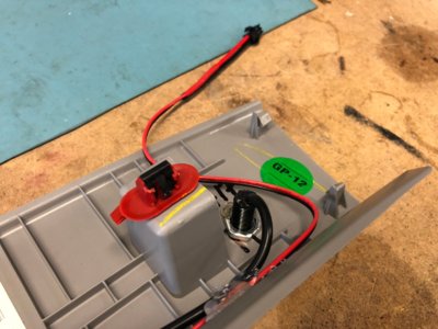
73impala
Full Access Member
I just spiced right into the rear wiring. I also wired the rear map lights to come on with the dome for more light
Kpwweb
Full Access Member
- Joined
- Dec 11, 2015
- Posts
- 698
- Reaction score
- 302
I love this forum and this thread is a great example why!
I’m finishing up my rear cargo light install with the help of everyone’s post here. This gave me the inspiration, courage to drill into my rig, and instructions.
Question: where did everyone pick up the ground? I saw the picks in the posts and it looks like some are using the stud for the amplifier? What size is the stud—4 mm?
I need to pick up a couple of ring connectors and a nut, I just don’t want 50 of the wrong size!
Thanks to everyone here for taking the time to help the rest of us! It is greatly appreciated!
gooffeyguy
Tom
The 2015+ has a higher cargo floor, the 3rd row seats fold flat into it.looks awesome, did you fabricate the floor pieces too ? i have a 2014 tahoe and don't realy use my back rear seats and wanted to build some sort of floor covering so it would be smooth like yours .
I'm trying to figure out how you got the new wires past the connector to get into that conduit for the liftgate wiring. I'm trying to do figureout a path for my rear dashcam wire, and this mod looks so awesome, I want to do the led light in the tailgate also!Since I was going to have lights mounted both inside the cargo area and under/behind the liftgate, I decided to place my switches on the panel above the liftgate window. So I ran the power and ground wires up through a conduit that leads from (a) the passenger side of the header area above the rear of the cargo area to (b) the center of the top of the liftgate just inside the window. I then ran another wire back down to connect Switch 1 to the 4 interior LEDs.
View media item 26837
Similar threads
- Replies
- 6
- Views
- 906
- Replies
- 3
- Views
- 561
