ScottyBoy
Full Access Member
Ok, most of you have already seen my thread on how to change the color of you power window switches by adding LED's. Now heres how to do basically the same thing to your AC control panel.
First off, remove the AC control panel from the truck. Now carefully pop off the 3 control knobs. Now open up the switch by removing the four 1/4 inch hex screws on the back.
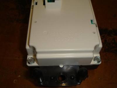
Now carefully release the tabs holding the circuit board in the white part of the contol panel, work your way around until it comes loose.
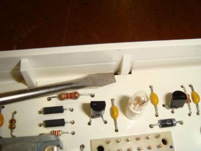
You can also unscrew the bottom board from the front panel by unscrewing the two 1/4inch hex scews.
The 4 stock bulbs on the bigger circuit board are wired in two pairs. Each pair is wired in series. So you will need to unsolder all 4 bulbs and on the two that I have circled, put a 330ohm resistor on the positive lead.
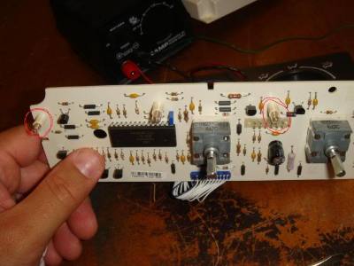
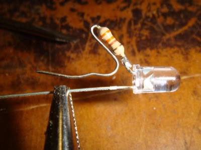
Here is how you want to configure the resistor into place. So it will line up the the two pinholes in the circuit board just like the stock bulb.
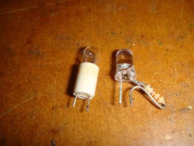
Stock bulb on the left, LED and resitor on the right.
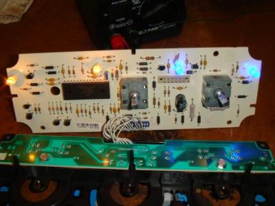
After you solder in your LED's with resistors, follow the tracer on the circuit board to the bulb next to it. That pin is where you will solder in your positive lead for the next LED, ground in the other pinhole. Here is a shot with the two right ones done.
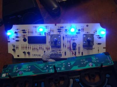
Now all four done.
Now you can move on to the smaller lower panel which lights up the buttons.
I've seen other sites say to do these with 3mm LED's (as the stock bulbs are about 3mm) but I put 5mm LED's and they fit just fine.
For the lower panel, you will need to solder in a 330 ohm resistor inline in the second wire from the right. This wire feeds the positive to all four of these bulbs.
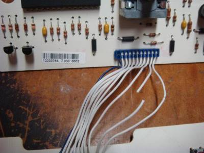
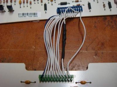
Now simply unsolder the stock bulbs, and solder the LED's in their place. The thin tracer wire on each bulb is the positive lead. On these, I had to do a little trial and error getting the LED's tilted on a slight angle to fire at the button for the best possible light output to each switch. Heres the LED's in place.
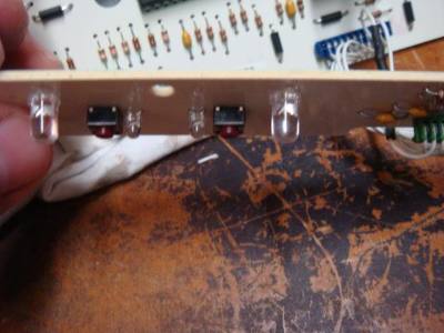
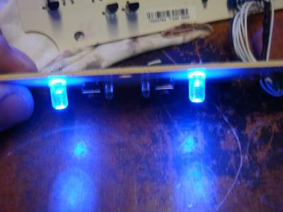
Now all are done.
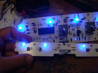
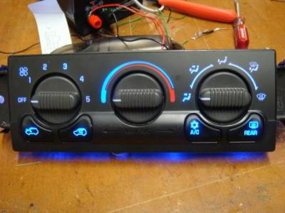
Now you can put the switch back together and go check it out in your truck. Here is a pic of me testing it on my 12v power supply.
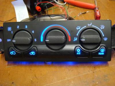
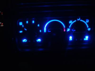
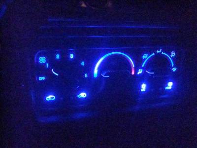
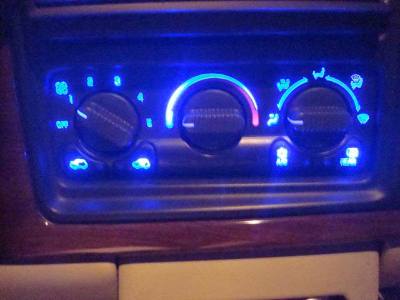
Here are a few pics of mine installed. The pics are crappy, I couldn't get the glare off the camera for shit! These pics do it no justice.
First off, remove the AC control panel from the truck. Now carefully pop off the 3 control knobs. Now open up the switch by removing the four 1/4 inch hex screws on the back.

Now carefully release the tabs holding the circuit board in the white part of the contol panel, work your way around until it comes loose.

You can also unscrew the bottom board from the front panel by unscrewing the two 1/4inch hex scews.
The 4 stock bulbs on the bigger circuit board are wired in two pairs. Each pair is wired in series. So you will need to unsolder all 4 bulbs and on the two that I have circled, put a 330ohm resistor on the positive lead.

Here is how you want to configure the resistor into place. So it will line up the the two pinholes in the circuit board just like the stock bulb.

Stock bulb on the left, LED and resitor on the right.

After you solder in your LED's with resistors, follow the tracer on the circuit board to the bulb next to it. That pin is where you will solder in your positive lead for the next LED, ground in the other pinhole. Here is a shot with the two right ones done.

Now all four done.

Now you can move on to the smaller lower panel which lights up the buttons.
I've seen other sites say to do these with 3mm LED's (as the stock bulbs are about 3mm) but I put 5mm LED's and they fit just fine.
For the lower panel, you will need to solder in a 330 ohm resistor inline in the second wire from the right. This wire feeds the positive to all four of these bulbs.


Now simply unsolder the stock bulbs, and solder the LED's in their place. The thin tracer wire on each bulb is the positive lead. On these, I had to do a little trial and error getting the LED's tilted on a slight angle to fire at the button for the best possible light output to each switch. Heres the LED's in place.


Now all are done.

Now you can put the switch back together and go check it out in your truck. Here is a pic of me testing it on my 12v power supply.

Here are a few pics of mine installed. The pics are crappy, I couldn't get the glare off the camera for shit! These pics do it no justice.


