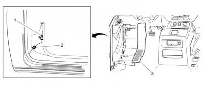
Received the following instructions. A bit more involved than I had originally thought...
1.Remove the left and right front side door sill garnish moldings.
Refer to Vehicle Service Manual.
2.Remove the left rear side door sill garnish molding.
Refer to Vehicle Service Manual.
3.Remove the left center pillar lower trim panel.
Refer to Vehicle Service Manual.
4.Remove the left front floor console extension panel, if equipped.
Refer to Vehicle Service Manual.
5.Remove the instrument panel knee bolster.
Refer to Vehicle Service Manual.
6.Remove the instrument panel insulator.
Refer to Vehicle Service Manual.

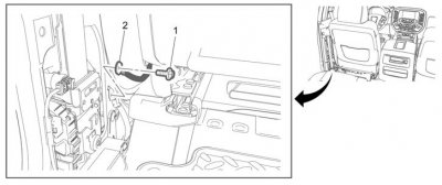
7.Remove the left center pillar ground screw (1).
Caution: Use the correct fastener in the correct location. Replacement fasteners must be the correct part number for that application. Fasteners requiring replacement or fasteners requiring the use of thread locking compound or sealant are identified in the service procedure. Do not use paints, lubricants, or corrosion inhibitors on fasteners or fastener joint surfaces unless specified. These coatings affect fastener torque and joint clamping force and may damage the fastener. Use the correct tightening sequence and specifications when installing fasteners in order to avoid damage to parts and systems.
8.Attach accessory harness ground eyelet (2) to the left center pillar and secure with the ground screw.
Tighten
Tighten the ground screw to 25 N.m (18 lb ft)

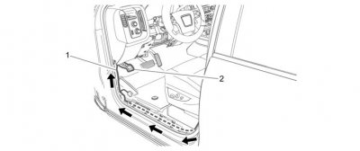
9.Rout the accessory harness (1) through the harness sill and sheet metal.
Tie wrap accessory harness to body harness at sill branch.
10.Continue to route accessory harness on top of body harness to I/P harness above the park brake mechanism (2).
Tie strap accessory harness to the left cowl at the low and high side.

11.Route accessory harness wire up to the BCM.
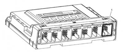
12.Remove the GRAY BCM connector 7 (1).
13.Remove circuit #157 (GRAY) from cavity 1 and cut off the terminal.
14.Strip the cut wire and insert into the PINK splice sleeve on the accessory harness.
15.Crimp the wire in the PINK splice sleeve and heat both ends of splice with heat gun.
16.Insert GRAY circuit into cavity 1 and reconnect to the BCM.
 Note:
Note: GMC vehicles have console, Chevrolet does not. Harness routing works on both vehicles.
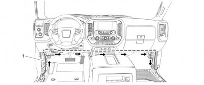
17.Continue to route accessory harness (1) along the HVAC duct on the driver’s side of the I/P, (a typical service routing).
18.Cross the center of the vehicle forward of the steel I/P to floor console brace, use three 12” tie straps or doubled up 8” tie straps on the left, center and right side of the HVAC duct.
19.Tie strap the accessory harness to the body harness forward of the sill trough.

20.Connect the front side door sill trim plate harness connector (1) to the power supply connector (2) into the new front side door sill trim plates (3).
Do not fully install the sill trim plates yet.
21.Move the sill plates away from the door opening. Close the doors to reset the lighting time out. Open the doors and confirm the illuminated sill plates are functioning.
22.Confirm that all wire routing are hidden. Secure all tie straps and cut off the tails.
23.Re-assemble all removed trim components to vehicle.
24.Verify that no wiring is visible or interfering with anything.
25.A total of seven areas will have wiring tie strapped into position.
Front of each sill plate; Qty: 2
High on the left side of cowl; Qty: 1
Left, center and right on driver’s HVAC duct; Qty: 3 – 12” straps
Right edge of the floor console, if equipped; Qty: 1

