electro
Full Access Member
Hi guys/gals,
I've taken my intake manifold/injectors out to replace a knock sensor that was setting code P0332... I found it easier and safer to remove first the injectors and than the Intake Manifold. Vin: Z trucks are E85 capable and the injector O-rings for these are not available seperatley and so if your break an O-ring you are required to purchase a new injector to get the O-ring...I'm sure you can match up an aftermarket O-ring...You just want to ensure a snug fit. That being said I chose to remove the fuel rail and intake manifold seperately.
When I finally removed the rubber boot that it is supposed to seal water out, the knock sensor (bank 2) basically snapped in two and fell over. Its clearly corroeded and ruined. Pictures to follow. (I cleaned valley cover and gasket surfaces up before I touched the Knock Sensor.)
Bad Knock Sensor, bank 2. Code: P0332.

Good Knock Sensor, bank 1. No code. I cracked the good knock sensor trying to remove the electrical connector...Oh well I purchased two new knock sensors anyways.

How to remove Knock Sesnor Electrical Connector...
Pinch the connector with needle nose in the directions indicated by arrows.

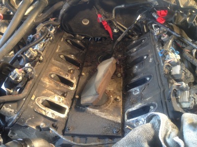
This is what I was looking at after removing Intake Manifold. Just a real mess, you can see why the sensor was corroded.
How to prevent future sensor corrosion...

Thanks!
1. Remove air intake, fan shroud, alternator, engine sight sheild, upper engine wiring harness, evap vent tube, fuel pressure regulator vacuum line, brake booster vacuum line, iac elec. conn., tps elec. conn., fuel injector elec. conn. (be sure to label to ensure proper reinstallation and correct firing order)
2. Relieve fuel pressure.
3. Remove fuel rail assembly.
4. Remove intake manifold.
5. Plug intake ports to prevent debris from entering combustion chamber. Use shop vac to remove said debris.
6. Clean Intake Manifold gasket mating surface and valley cover, be carefull not to scratch aluminum - could result in poor Manifold seal.
7. Remove KS. (22mm)
8. Replace KS and tighten to (15 lb ft.).
9. Using RTV sealant build a dam around knock sensor cavity to divert water away. 3/8" wide and 1/4" high bead of RTV.
10. Install intake manifold. Apply medium strength thread locker and tighten manifold bolts in sequence first pass to 49 in lbs and than second pass to 89in lbs.
11. Install fuel rail and connect injector electrical connectors to proper injector to ensure correct injector firing order.
I've taken my intake manifold/injectors out to replace a knock sensor that was setting code P0332... I found it easier and safer to remove first the injectors and than the Intake Manifold. Vin: Z trucks are E85 capable and the injector O-rings for these are not available seperatley and so if your break an O-ring you are required to purchase a new injector to get the O-ring...I'm sure you can match up an aftermarket O-ring...You just want to ensure a snug fit. That being said I chose to remove the fuel rail and intake manifold seperately.
When I finally removed the rubber boot that it is supposed to seal water out, the knock sensor (bank 2) basically snapped in two and fell over. Its clearly corroeded and ruined. Pictures to follow. (I cleaned valley cover and gasket surfaces up before I touched the Knock Sensor.)
Bad Knock Sensor, bank 2. Code: P0332.

Good Knock Sensor, bank 1. No code. I cracked the good knock sensor trying to remove the electrical connector...Oh well I purchased two new knock sensors anyways.

How to remove Knock Sesnor Electrical Connector...
Pinch the connector with needle nose in the directions indicated by arrows.

This is what I was looking at after removing Intake Manifold. Just a real mess, you can see why the sensor was corroded.

How to prevent future sensor corrosion...

Thanks!
1. Remove air intake, fan shroud, alternator, engine sight sheild, upper engine wiring harness, evap vent tube, fuel pressure regulator vacuum line, brake booster vacuum line, iac elec. conn., tps elec. conn., fuel injector elec. conn. (be sure to label to ensure proper reinstallation and correct firing order)
2. Relieve fuel pressure.
3. Remove fuel rail assembly.
4. Remove intake manifold.
5. Plug intake ports to prevent debris from entering combustion chamber. Use shop vac to remove said debris.
6. Clean Intake Manifold gasket mating surface and valley cover, be carefull not to scratch aluminum - could result in poor Manifold seal.
7. Remove KS. (22mm)
8. Replace KS and tighten to (15 lb ft.).
9. Using RTV sealant build a dam around knock sensor cavity to divert water away. 3/8" wide and 1/4" high bead of RTV.
10. Install intake manifold. Apply medium strength thread locker and tighten manifold bolts in sequence first pass to 49 in lbs and than second pass to 89in lbs.
11. Install fuel rail and connect injector electrical connectors to proper injector to ensure correct injector firing order.
Last edited:
