Rigid SAE Fog Lights as DRLs (23 Denali)

Disclaimer: Links on this page pointing to Amazon, eBay and other sites may include affiliate code. If you click them and make a purchase, we may earn a small commission.

OP
OP
BobHolthaus

BobHolthaus

Member
Joined
May 2, 2023
Posts
96
Reaction score
53
At least on the 2022+ Sierra, the fog lights are powered by a single pin (X1-6) from the lighting control module. BA is using the left front parking light power (X1-1) to power both fog lights through their jumper, which is likely a diode (directional).

The Yukon uses separate pins (on different connectors) from the LCM to power the fog lights (X1-3 (left) and X3-2 (right)). I suspect this indicates the Yukon fog lights draw more power than the Sierra fog lights. It should be possible to do a similar mod on a Yukon, but a bit more involved than the Sierra, both in parts required and installation effort. The Yukon modification community is also a fraction of the size of the pickup modification community so likely not a worthwhile investment.
Thank you for this explanation. Makes total sense. I’m guessing the two connector points you mention above are under the dash, like on a Sierra? I am capable of doing this mod; not sure I want to tackle it, but I get it (and yes I agree on the diode). Thanks again.
 

jgraves

Full Access Member
Joined
Nov 19, 2021
Posts
121
Reaction score
78
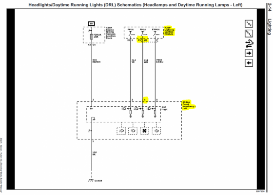
Check out https://www.gmupfitter.com/body-builder-manuals/ for schematics and connector tables. For instance there is a system schematic for the headlights and another for the for lights. Both reference lighting control module (K219). Later in the document there is a table describing the location of all the modules, and a page with the pin assignment for each connector of that module.

If I were tackling this, I would isolate the loads from the LCM. For instance, a diode to prevent backdriving the fog light circuit, a relay to avoid pulling the fog light current through the park light circuit, and a flyback diode on the relay coil.
 

jgraves

Full Access Member
Joined
Nov 19, 2021
Posts
121
Reaction score
78
I feel I'm getting closer to figuring this out after studying the schematics for a couple evenings. I'm attempting add driving lights activated with high beams, aux reverse lights activated with reverse lights and additional cargo area / rear hatch lights activated with the cargo area light, with at least the first 2 on manual, arm/auto and off switches, while being minimally invasive to the factory wiring.

So far I've located PWM controls all 3 lights (in addition to momentary ground signals for high beam and flash to pass) in the schematics and connector diagrams. I've also physically identified the body and lighting control modules in the truck. They're both mounted vertically on the left wall, under the steering column, left of the brake pedal. The LCM is mounted directly to left wall and has 5 connectors. The BCM is mounted on top (closer to the brake pedal) of the LCM (closer to the brake pedal) and has 8 connectors.

Assuming all PWM controls are approximately 12V while active, my next step will be to (temporarily) drive relays from them and watch for error messages. If they're noticeably less than 12V or driving the relay directly causes an error, I'll find or build an optocouple based relay control circuit.

Edit to correct location of BCM and LCM. They were reversed in my original post.
 
Last edited:

jgraves

Full Access Member
Joined
Nov 19, 2021
Posts
121
Reaction score
78
So my wife left me home, unsupervised this evening. I went the the garage to poke around a bit and maybe probe a couple LCM pins, before making myself dinner. She came home around 7:30pm, while I was still in the garage, dropped off the all weather floor liners she got me for Christmas, laughed when I told her I would be in shortly and is now asleep. I'm writing this as I'm making dinner, at nearly 11:30pm.

I wasn't able to probe the LCM pins of interest from the back side of the connectors with the probes I have at home. I think I could with the needle like probes we have a work, but I'm not going to the office until Tuesday and I was fairly confident I wanted access to these signals, so I tapped X3-7 (right backup light) and X5-16 (right high beam). There are left side equivalents to both of these but these where slightly more accessible in my truck. X5-16 measured 11.7V with the high beams on and truck not running, which is fairly close to battery voltage. Touching the tap to a generic automotive relay cycled it without any error messages so I proceeded to wire 2 relays with flyback diodes.

The high beam relay powers the switch I previously installed for driving lights, resulting in "off" and "on with high beams". I want "off", "on with high beams" and "on" which will require a different (or second) switch. The reverse light relay has no load connected as I haven't purchased (or decided on) lights yet, but it cycles with reverse gear selection.

I've drove 20 minutes after buttoning this up (and looking for any takeout restaurant still open) with high beams on about half that time. Everything works as expected and no error messages.

I'm going to look for a cargo light tap point near the back of the truck, as I don't see any reason to have them switched from the dash.
 

K5-Z71

Member
Joined
Jan 5, 2023
Posts
51
Reaction score
88
Location
TX
Touching the tap to a generic automotive relay cycled it without any error messages so I proceeded to wire 2 relays with flyback diodes.

Sweet! I would have never thought to run a relay with the PWM signal, glad to hear it works!

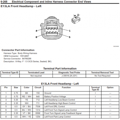
Would the high beam signal on X5-16 you tapped be the same as on the headlamp connecter E13LA Pin 4? This may be an easier location to get the signal from.

Headlamp Connector pin out.png
 

jgraves

Full Access Member
Joined
Nov 19, 2021
Posts
121
Reaction score
78
Disclaimer: It worked for a 20 minute drive last night. It is not proven reliable or risk free. Proceed at your own risk.

One last thing I'll stress is to use flyback diodes on all your relays. Failure to do so will result in voltage spikes when the relay is turned off. I blew fuses (fuse taps for lighting) in my previous truck before I understood the importance of flyback diodes. I would hate to see someone fry an expensive and possibly hard to get module following modifications I published. I will likely replace my mechanical relays with much smaller solid state relays eliminate this completely, reduce the current draw on the module and eliminate the click.

E13LA, Pin 4 corresponds to X5-28 which is the mirror of X5-16. Page 2-14 shows the E13LA-4 to K219-X5-28 connection while page 2-15 shows the E13RA-4 to K219-X5-16 connection.

1704488867120.png

I found accessing these signals at the LCM much more convenient for my installation. My relays activated by the LCM only enable my switches, and my switches (single at the moment) are installed in the removable dash panel by my left knee. If I mess up cutting a hole in the panel or want to remove the switches (and lights) to resell the truck, it is an inexpensive part to replace. None of my wire runs between the LCM, these relays and switches are more than 12" long. I have a second relay above the right front tire which powers the driving lights. There is unused space here, it's close to the battery, and I can follow all the factory grill / bumper cover wiring which passes behind / under the right headlight.
 

K5-Z71

Member
Joined
Jan 5, 2023
Posts
51
Reaction score
88
Location
TX
Working great for me as well, wired up just as jgraves advised. The LCM triggers a solid state relay mounted in the cabin which triggers a standard relay up near the light bar. Three way switch allows OFF - Full ON - Follow High Beams.

Does exactly what I wanted without all the craziness I came up with. Thanks for the help jgraves!
 

Forum statistics

Threads
133,293
Posts
1,883,006
Members
98,359
Latest member
Jacobamers
Top