03 tahoe LED dome light

Disclaimer: Links on this page pointing to Amazon, eBay and other sites may include affiliate code. If you click them and make a purchase, we may earn a small commission.

Rivieraracing

Full Access Member
Joined
May 2, 2009
Posts
3,810
Reaction score
82
Location
Oregon
That's a vintage piece of electrical ingenuity there Chauncey, might have to put that up in the Smithsonian!!! lol Actually, sometimes those work better for ohming than a digital meter does!! Gonna go out and ohm some bulbs right now, hopefully I still know how to do that!! Let's get this resistor trick going and see if it works!

---------- Post added at 02:27 PM ---------- Previous post was at 01:25 PM ----------

So Chauncey, here's what I got for ohms:

194's = 2.5 ohms
Festoon's = .8 ohms

These are regular bulbs, not LED's!! So, what do you think would work for a resistor?
Also, it's crazy that there was a voltage difference between manually turning a light on as opposed to opening a door. At least in my denali, at the front map/dome lights (mine are 194 bulbs), the voltage when manually turning on the light was slightly more than when the doors were open!
 

chauncey0337

Full Access Member
Joined
Jan 22, 2011
Posts
3,178
Reaction score
30
Location
MLT, WA
That's a vintage piece of electrical ingenuity there Chauncey, might have to put that up in the Smithsonian!!! lol Actually, sometimes those work better for ohming than a digital meter does!! Gonna go out and ohm some bulbs right now, hopefully I still know how to do that!! Let's get this resistor trick going and see if it works!

---------- Post added at 02:27 PM ---------- Previous post was at 01:25 PM ----------

So Chauncey, here's what I got for ohms:

194's = 2.5 ohms
Festoon's = .8 ohms

These are regular bulbs, not LED's!! So, what do you think would work for a resistor?
Also, it's crazy that there was a voltage difference between manually turning a light on as opposed to opening a door. At least in my denali, at the front map/dome lights (mine are 194 bulbs), the voltage when manually turning on the light was slightly more than when the doors were open!

Chris, are you sure those values are correct? That means each festoon bulb is drawing 15 amps? I don't think that's right. And for the map lights having more voltage when turned on manually might be because when you do the switch, the voltage is going straight through the switch and to the bulb. When the doors open the voltage has to go through the door switch and whatever else is involved in that circuit.
 

Rivieraracing

Full Access Member
Joined
May 2, 2009
Posts
3,810
Reaction score
82
Location
Oregon
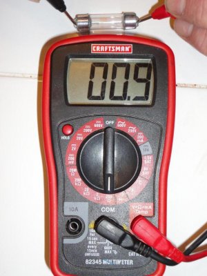
Here's another festoon bulb that I had in my garage and this is the setting on my multimeter and the reading I'm getting!!
 

Attachments

  • Bulb ohm.jpg
    Bulb ohm.jpg
    96.6 KB · Views: 12

RobertWYoung

Member
Joined
Aug 10, 2009
Posts
56
Reaction score
0
Location
Fort Worth
Neither of those make sense ... Here's a 194 spec sheet Link

A 194 should read around 51 ohms

---------- Post added at 07:39 PM ---------- Previous post was at 05:51 PM ----------

I went and pulled one out of my front and middle dome/map bulbs. The front little bulb (168) read 3.5ohms and the other one (578) read 1.4ohms. After further reading they increase in resistance as they heat up.
 
Last edited:

Rivieraracing

Full Access Member
Joined
May 2, 2009
Posts
3,810
Reaction score
82
Location
Oregon
Neither of those make sense ... Here's a 194 spec sheet Link

A 194 should read around 51 ohms

---------- Post added at 07:39 PM ---------- Previous post was at 05:51 PM ----------

I went and pulled one out of my front and middle dome/map bulbs. The front little bulb (168) read 3.5ohms and the other one (578) read 1.4ohms. After further reading they increase in resistance as they heat up.

So, I am reading the bulbs correctly, right? It's been a while that I have ohmed something for a value but I thought I was reading it right!

---------- Post added at 06:48 PM ---------- Previous post was at 06:47 PM ----------

By the way, thanks for taking the time out to help us check this stuff, can use all the help we can get to put this thread to rest with a fix!!:Handshake:
 

RobertWYoung

Member
Joined
Aug 10, 2009
Posts
56
Reaction score
0
Location
Fort Worth
Yes you are reading the bulb correctly ... Unfortunately there isn't a way to read its real ohmage (is that a word?)

But the spec sheets tell us they pull between 20 and 35 milliamps so if we set the led circuit to do the same we shouldn't have an issue.

The 8 volt reading bothers me more then the unknown resistance of the bulbs.

You can't set the current if the voltage jumps from 8 to 14.

---------- Post added at 09:43 PM ---------- Previous post was at 09:36 PM ----------

I'm going to put these bulbs back in and take some voltage readings ... I'll update with what the results are.

---------- Post added at 10:04 PM ---------- Previous post was at 09:43 PM ----------

Reading to the bulb contacts:

I got straight 12 volt readings on the battery and 14 volt readings with the engine on. Controlled with the door and the button on both the front and the 2nd row.
 

chauncey0337

Full Access Member
Joined
Jan 22, 2011
Posts
3,178
Reaction score
30
Location
MLT, WA
Neither of those make sense ... Here's a 194 spec sheet Link

A 194 should read around 51 ohms

---------- Post added at 07:39 PM ---------- Previous post was at 05:51 PM ----------

I went and pulled one out of my front and middle dome/map bulbs. The front little bulb (168) read 3.5ohms and the other one (578) read 1.4ohms. After further reading they increase in resistance as they heat up.

If a 194 should be 51 ohms, then it's pulling 235 milliamps at 12v. What you measured for your 168(194 same), it's pulling 3.42 amps at 12v. Something does not seem right. Going by what you said "they increase in resistance as they heat up", I think we need to test the resistance when bulbs are in and on if possible.

Yes you are reading the bulb correctly ... Unfortunately there isn't a way to read its real ohmage (is that a word?)

But the spec sheets tell us they pull between 20 and 35 milliamps so if we set the led circuit to do the same we shouldn't have an issue.

The 8 volt reading bothers me more then the unknown resistance of the bulbs.

You can't set the current if the voltage jumps from 8 to 14.

---------- Post added at 09:43 PM ---------- Previous post was at 09:36 PM ----------

I'm going to put these bulbs back in and take some voltage readings ... I'll update with what the results are.

Going by spec sheet, pulling 20 ma at 14v, resistance of bulb is 700 ohms.
Pulling 35 ma at 14v, resistance of bulb is 400 ohms.
 

RobertWYoung

Member
Joined
Aug 10, 2009
Posts
56
Reaction score
0
Location
Fort Worth
E / I = R
14v / 0.271A = 51.66ohms

Which is what the 194 spec sheet says. I did say that wrong earlier I missed a zero; 271mA not 27mA.

The 168 spec sheet said 0.357A with a resistance of 39.2 ohms.

You can't read resistance with anything in or on.

With that info you can add resistors to pull the proper amount of current to fix the issue but you have to know the draw of the LED in question.

---------- Post added at 11:11 PM ---------- Previous post was at 10:24 PM ----------

I'm still more concerned about why they are getting a voltage drop.

I would pull the bulbs, at least all the LEDs and measure the voltage again.

The relay buzzing sounds like it might be the BCM switching. I doubt the relay is fast enough "dim" with the BCM.

---------- Post added at 11:40 PM ---------- Previous post was at 11:11 PM ----------

Tomorrow I will connect my meter in series to read current and see what the bulbs pull.
 

JochenWoern

Full Access Member
Joined
Sep 29, 2011
Posts
2,427
Reaction score
18
Location
Sacramento, CA
That's what Chauncey and I are discussing as well, and are wondering if adding a resistor to a LED bulb that's equivalent to the natural resistance of a regular bulb would solve the problem you guys are having!! I think Chauncey was going to ohm a regular bulb to find out the resistance of that bulb and find a resistor that is the same resistance and see if that works instead of adding an additional wire to each light to "up" the voltage!!
If you think about it, could you ask the same engineer what I just mentioned now and see what he thinks about that idea, curious on if he thinks that by adding a resistor to up the load needed to power the LED if that would work?

Man, oh man, does my newly discovered Harvard brain hurt right now!!! lol

OK Chris, talked to the Engineer again and he thinks that a Resistor (if done corrctly and the proper/correct Resistor is chosen) will work.
 

Forum statistics

Threads
132,728
Posts
1,873,275
Members
97,558
Latest member
BurbyRST

Latest posts

Top