2021 PPV Front Brakes on 2013 Escalade ESV, and rear brake overhaul

Disclaimer: Links on this page pointing to Amazon, eBay and other sites may include affiliate code. If you click them and make a purchase, we may earn a small commission.

OP
OP
skpyle

skpyle

Full Access Member
Joined
May 15, 2021
Posts
412
Reaction score
1,081
With the 'figure out how to make stuff fit' part done, the rest was to be straight bolt-on. (More ominous thunder...)

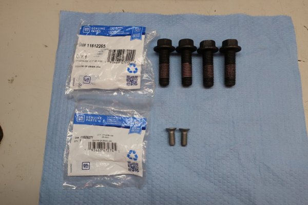
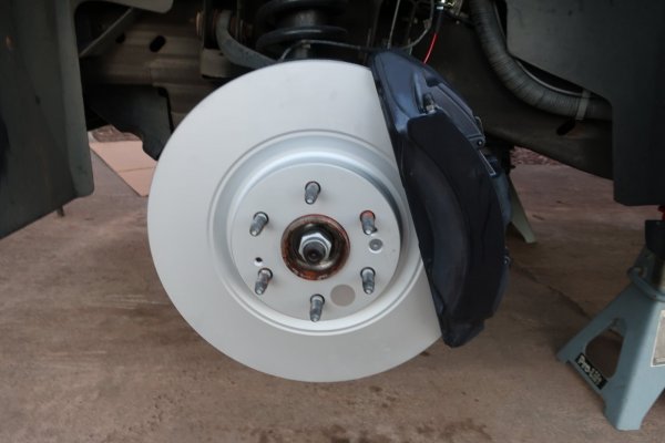
I installed the new Power Stop AR82209EVC Evolution fully coated 16" rotors with new GM Genuine 11609271 rotor retaining screws onto the front wheel hubs. I put a thin layer of copper antiseize on the hub face and a touch on the retaining screws. Note, the rotor retaining screws are the same as the stock 2013 Escalade parts.
Also...these rotors are quite heavy!


2024-02-15 045.JPG
New 16" rotor looks huge!


2024-02-15 032.JPG
New 11609271 rotor retaining screws under new 11612265 caliper mounting bolts.


Assembly and installation time for the calipers.

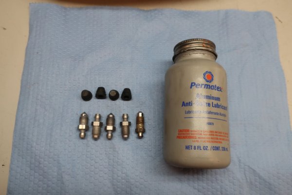
I removed all four bleeder screws from both calipers so I could put a touch of silver antisieze on the threads.


2024-02-15 030.JPG
All four bleeder screws from the new GM/Brembo 6-piston calipers with rubber caps. A bleeder screw from the stock GM 2-piston caliper is at right for comparison. The thread pitch is different.


2024-02-15 031.JPG
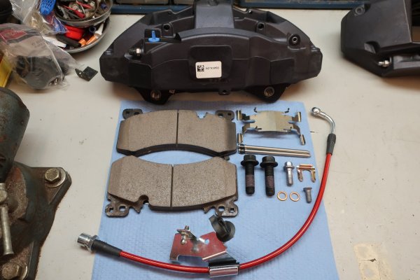
Caliper parts laid out for assembly.


2024-02-15 033.JPG
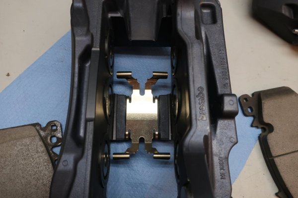
Start off by installing the pads tensioning spring into the body bridge of the caliper.
 
Last edited:
OP
OP
skpyle

skpyle

Full Access Member
Joined
May 15, 2021
Posts
412
Reaction score
1,081
2024-02-15 034.JPG

2024-02-15 035.JPG
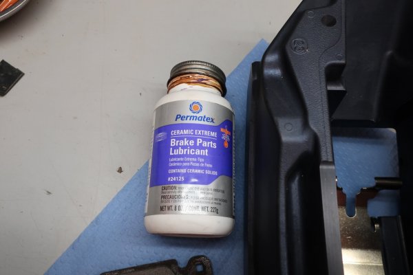
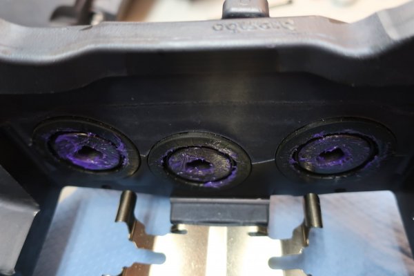
Put a layer of Permatex purple ceramic brake parts lubricant on the piston faces to help keep the pads from squeaking.


2024-02-15 036.JPG
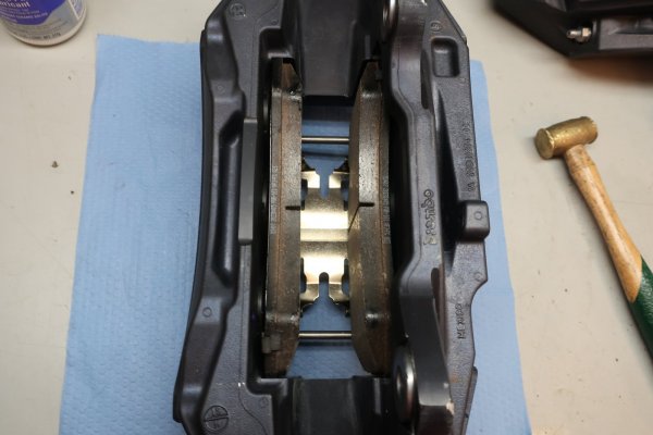
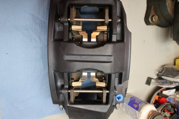
The Power Stop Z232407 Z23 Carbon Fiber-Ceramic brake pads are identical and go in either side. Slide them in, push them down to compress the tension spring, then push the bottom edge of the pad onto the little ledge machined into either side of the caliper piston area.


2024-02-15 040.JPG
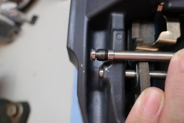
Next trick is to install and seat the pad retaining pins. What worked best for me is to have the caliper laying on its bridge, with the pads facing up. Start a pin into the caliper hole on the inboard side, push down that end of the inboard pad until the pin passes through the hole in the pad. Push the pin through to the outboard pad, push down on that end of the outboard pad until the pin passes through the hole in the pad. Continue pushing down on the brake pad until the pin will pass through the caliper hole on the outboard side. Then use a small hammer and punch to seat the pin by compressing the little metal spring bushing.
Repeat for the other pin.
Ignore the marks from me trying to be slick and using a small brass hammer to seat the pin. My aim and accuracy are not as good as I thought...


2024-02-15 037.JPG
This is what the pins and pads look like when properly installed.

I did NOT use any brake parts lubricant on the pins. The holes in the pads are larger than the pins, and loosely guide the pads. They are not like the slider guide pins in the stock 2-piston floating caliper. Plus, there are no boots or anything. In my mind, any lubricant on those pins will end up on the pads and rotors.

Looking back, I could have put a tiny amount of lubricant in the caliper pin holes to prevent corrosion.
 
Last edited:
OP
OP
skpyle

skpyle

Full Access Member
Joined
May 15, 2021
Posts
412
Reaction score
1,081
I mounted the assembled brake calipers with the new mounting bolts and correct spacers.
The mounting bolts and spacers were fiddly because the spacers had to go between the caliper mounting ears and the spindle.

When I was mocking up the calipers for fitment, the rotors were not installed. I had clearance for my fingers to keep the spacers from falling off the bolts while mounting the calipers. No such animal with the rotors installed.

What I finally figured out was to push the bolts through the mounting ears on the spindle then slide the washers onto the bolt threads. Then set the caliper over the rotor. Line up the top mounting ear with its bolt and lightly hold the ear casting against the bolt. Start slowly and carefully pulling the bolt back through the spindle mounting ear. As I did this, I kept feeling for the bolt to 'clear' the caliper ear casting. As soon as it did, I pushed the caliper down and the bolt back in. This kept the spacer washers trapped and prevented them from falling. Then it was just a matter of wiggling the caliper around until the mounting bolt started in the hole. Thread the bolt in and breathe a sigh of relief.

Repeat 3 more times.
It took me a few times to get this right.

I ran the bolts in with my battery ratchet. Then torqued them to 80 lbs/ft, then 148 lbs/feet. I don't know if it matters which bolt got torqued first, top or bottom. I started with the top.


2024-02-15 059.JPG
Installed driver's side caliper.


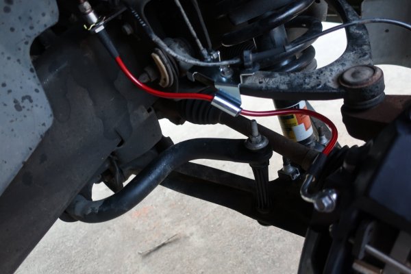
Calipers mounted, next step was to install the front braided steel brake hoses from the Power Stop BH00161 hose kit. These went on pretty smoothly, though I had to pay attention to which hose went to which side. The support brackets that bolt to the trailing edge of the control arms are side specific, as well as the bend in the banjo fitting at the end of the hose.


The ends of the brake hoses do not key into the mounting tabs on the frame. So, I loosely installed the banjo fitting on the caliper with two new 21012386 copper crush washers. These are also stock for 2013 Escalade. I did not use the copper crush washers supplied with the Power Stop kit because the GM washers were thicker. Also, I used the shortened GM banjo bolts from post #3 in this thread.

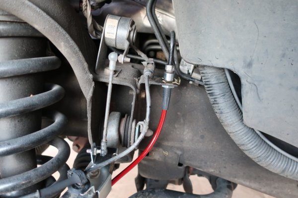
I then put a little copper antiseize on the metal brake line itself down near the flare and on the brake line B-nut threads. Then loosely threaded the brake line into the end of the new brake hose.

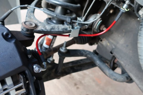
Then bolted the brake hose support bracket to the trailing edge of the upper control arm. Pushed the brake hose end into the mounting tab on the frame and installed the retaining clip supplied with the Power Stop kit. Then tightened the brake line B-nut to the brake hose.

The banjo fittings caused me a bit of consternation. Power Stop kit instructions call to torque the banjo bolts to stock specifications, which is 31 lbs/ft for a 2013 Escalade. Go to post #4 in this thread and note that the banjo fittings on the brake hoses are not very thick. As I torqued the first banjo bolt, the torque wrench just wasn't clicking. I was very concerned about crushing the banjo fitting. So, I backed the torque wrench down to 15 lbs/ft. Click. 20 lbs/ft. Click. 25 lbs/ft. Click. 31 lbs/ft. Pull... OK, we are done. I torqued the other banjo bolt to a little past 25 lbs/ft.
So far, they don't leak.
If they do leak, I will look into just installing stock replacement brake hoses. The banjo fittings are MUCH thicker.

Also, while I was torquing the banjo bolts, I tried to align the brake hose coming off the caliper so the hose was at a 'natural' angle. I should have also given consideration to getting an 18mm socket on the caliper mounting bolts in the future. It fits, but I have to bend the hose out of the way sharply. Something to keep in mind...


2024-02-15 063.JPG
Driver's side brake hose connected to the brake line.


2024-02-15 062.JPG
Driver's side brake hose to the caliper, and the support bracket. Photo makes it look like the hose is rubbing the underside of the upper control arm. It is not. Plus, the suspension is at full droop. At ride height, the hose is free and clear.


2024-02-15 067.JPG
Passenger's side brake hose. I don't know why the support bracket is angled instead of straight as on the driver's side.
 
OP
OP
skpyle

skpyle

Full Access Member
Joined
May 15, 2021
Posts
412
Reaction score
1,081
While getting my pressure bleeder set up and doing general clean-up, I let the calipers gravity bleed for awhile. Didn't really do much. :(

With my pressure bleeder, I started at the inside bleeder on each caliper, and bled a full bottle(not bottle of brake fluid, but bottle on my little bleeder kit that connects to the caliper bleeder screw). Then did the same for the outer bleeder screw on each caliper. All four bleeder screws bled well and had no additional air after the initial surge.

I will be replacing the rear brakes in the near future, and will bleed the fronts again as part of that process.

Bleeding done, last step was some corrosion prevention. I grew up in Ohio, and cut my teeth on rusty death traps. That has colored how I view vehicles.

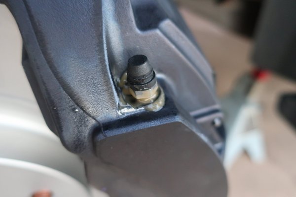
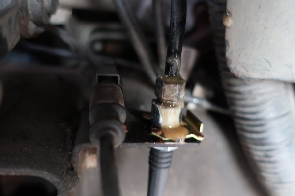
I sprayed each bleeder screw base and the entire B-nut/brake hose junction with a layer of Fluid Film. Ugly - yes. Less likely to corrode and seize - also yes.


2024-02-15 069.JPG
Fluid Film on bleeder screw base.


2024-02-15 071.JPG
Fluid Film on brake line/hose connection.


And this brings us to where I thought I was done. And it all went wrong when the front wheels did not fit...(Ominous thunder arrives)
 
OP
OP
skpyle

skpyle

Full Access Member
Joined
May 15, 2021
Posts
412
Reaction score
1,081
It is great to see that the Powerstop 2021-2023 PPV rotors are available!

I had the same problem with wheel clearance for my 2011 Yukon Denali wheels, so I ended up using .250 hub centric spacers from Baer. I don't like having the wheel non-hub centric, but the braking is awesome.
Agreed. When I was researching this project, I saw reports that rotors from various manufacturers were in short supply.
 
OP
OP
skpyle

skpyle

Full Access Member
Joined
May 15, 2021
Posts
412
Reaction score
1,081
Alright, we have established that the new calipers are too fat for the stock wheels to fit.
Spacers and longer lug studs are needed.

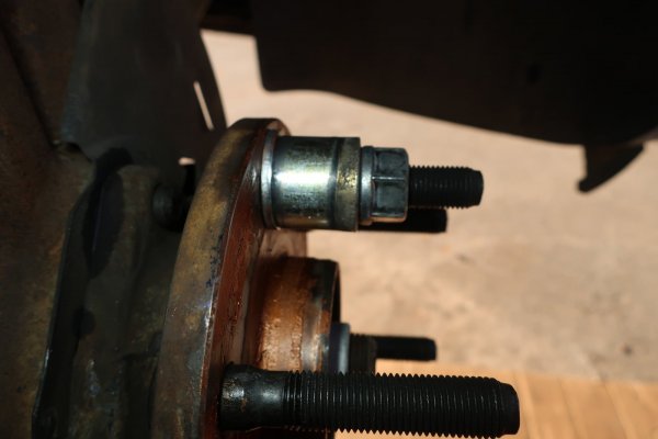
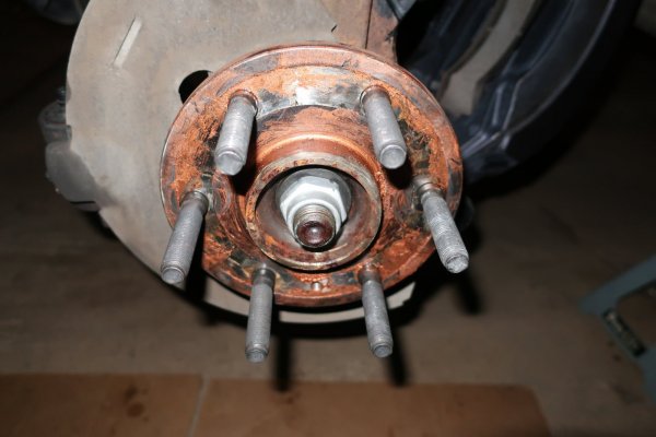
The front lug studs have the following dimensions:
GM 11603331
Thread: M14x1.5
Knurl dia: 15.8mm (0.623")
Shoulder length: 0.638" (16.2mm)
Thread length: 31mm
Underhead length: 65.405mm (2.575")
Quick start nose: Yes

Of these dimensions, Knurl diameter and underhead length are the two that matter most.

I dug around on the internet and came up with these lug studs:
Dorman 610-530
Thread: M14x1.5
Knurl dia: 15.9mm (0.625")
Shoulder length: 1.008" (16.2mm)
Thread length: 48.4mm
Underhead length: 78mm (3.07")
Quick start nose: No

I ordered 12 of them.
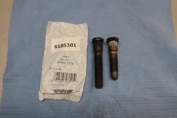


2024-02-28 001.JPG
Dorman 610-530.1 lug studs. I found these spec'd out for the rear of a Ford F350 dually. ;)


I have new lug studs. OK, great. Now to change them. Should not be too bad. AllDataDIY service manual states (paraphrasing) remove brake caliper, remove brake rotor, press out old stud with ball joint press, use lug nut and stack of washers to pull new stud in.

WRONG.
In
So
Many
Ways...

I wasted time searching for different lug stud removal and installation tools. Ball joint press was a no-brainer, as I already had one. Only tools I saw for installation pretty much replaced the stack of washers with a sleeve and bearing. I screwed up and took to heart an article I read. It stated that pulling the new stud in with a lug nut and stack of washers can stretch/damage the threads on the stud. A better idea is to use a ball joint separator to push the stud in from behind the wheel flange.
That seemed like a REALLY good idea to me.

Having done this, that was a really BAD idea. Rereading the article, the author was working on a Toyota Corolla. M12 lug studs. GMT900's use M14 lug studs.
Idiot


Anyway, I got the calipers and rotors back off. As an aside, I am glad I did NOT use the M14x2.0 - 40mm TTY mounting bolts. I would have had to buy another set.

Looking at the casting of the spindle, I had the most room to work with in terms of using the ball joint removal tool by placing the lug stud in question at about the 10-11 o'clock position. Until I realized the base of my ball joint tool was too thick to fit behind the wheel flange. :banghead:

I tried various stupid ideas that reinforced my knowledge of offset vectors. IE angled push launched spacer at my head.
Staring at it long enough, I decided the only thing I could do was unbolt the hub and see if I had enough clearance then.

Luckily, I did. The outer CV joint had enough in-n-out movement to allow me to **** the wheel bearing hub to JUST get enough clearance to get the base of the ball joint press behind the wheel flange. Mind you, those wheel hub bolts were quite tight!
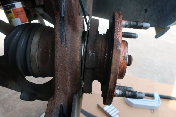


2024-02-28 002.JPG
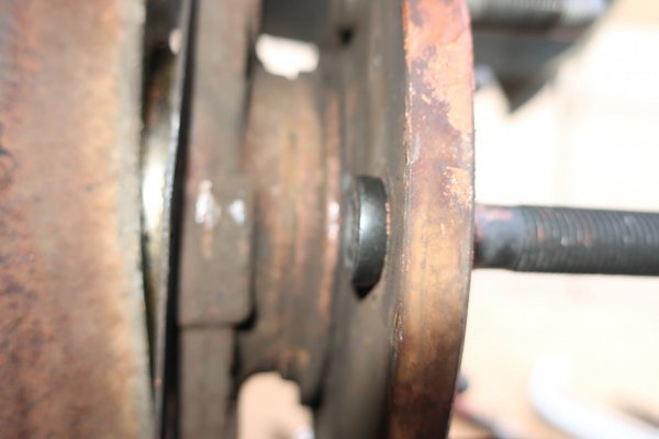
Passenger's side front wheel bearing hub unbolted and cocked for clearance.


Using the ball joint press was not too bad to press out the original lug studs. The base did not sit 100% flat on the back of the wheel flange, but it was close enough. I just had to ensure the tip of the forcing screw was centered on the round nose of the stud. I used my battery impact to drive the forcing screw and push the stud out. Did not slip off for any of the 12 studs.
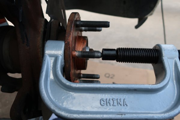


2024-02-28 007.JPG
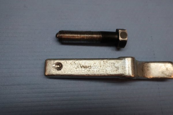
Chinesium ball joint press used to press the old lug studs out of the wheel flange.


All this extra work does beg the question: why didn't I just beat the old lug studs out with a hammer? Because my luck says the 154,*** mile wheel bearings would not like it. Also, I don't know if there would have been sufficient room to slide the new lug studs into the wheel flange for installation.


Installing the new longer lug studs was a b*tch in high heels. In theory, the ball joint separator would work fine to push the studs in. In practice, not so much.
I learned a few things along the way:
-lubricate splines with AeroKroil to assist pulling in
-start stud with just the ball joint separator, then put a large nut behind the head of the stud and push it home. This is due to how the tool works at a decreasing angle
-getting the large nut spacer to stay on the back of the stud and not come flying out at me was hit or miss. I got hit alot.
-clean and relubricate the forcing screw threads with synthetic wheel bearing grease for each lug stud
-new curse words to assist the tool

I finally got all 12 lug studs in. Though the tool suffered. Badly.
I was very concerned about completely stripping the threads on the forcing screw, so I did not let the impact linger when I thought the stud was seated at the wheel flange. As a little insurance, I set up a spacer, washer, and lug nut on each stud. Then gave the lug nut a blast from the impact. Just to ensure the new lug studs were fully seated.
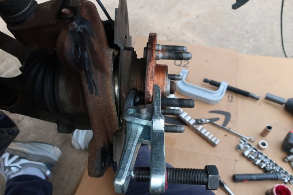


2024-02-28 004.JPG
Using ball joint separator tool to initially start the new lug studs.
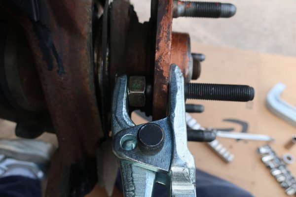


2024-02-28 005.JPG
Spacer nut behind the head of the new lug stud to help the ball joint separator fully seat the stud. And occasionally shoot out at my head.
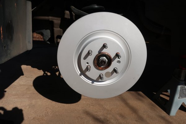
 
Last edited:
OP
OP
skpyle

skpyle

Full Access Member
Joined
May 15, 2021
Posts
412
Reaction score
1,081
2024-02-28 006.JPG
I didn't feel like the ball joint separator fully seated the new lug stud.
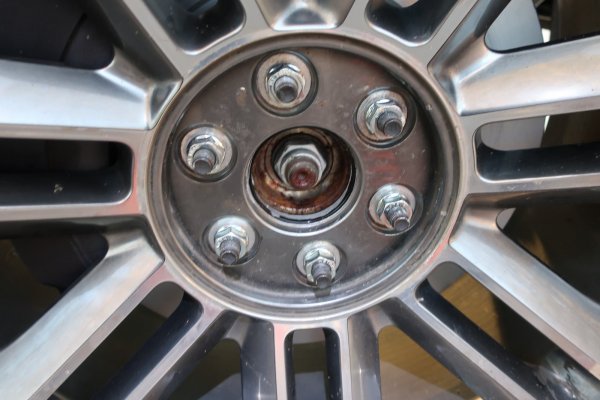


2024-02-28 012.JPG
Washer, spacer, and lug nut used to fully seat the new lug stud.
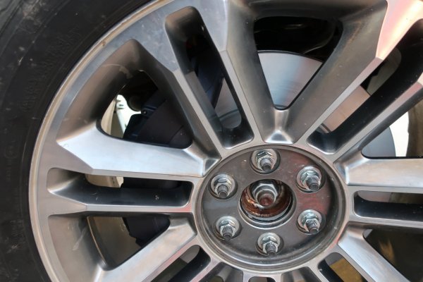


2024-02-28 024.JPG
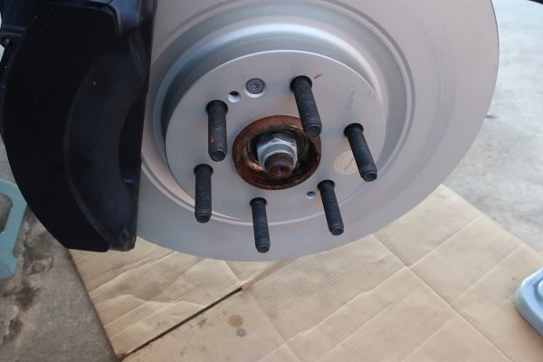
6 longer lug studs installed in driver's side wheel flange.


I cleaned the wheel bearing hub mounting bolts then reinstalled them with blue threadlocker. Torqued them down to 80 lbs/ft then 133 lbs/ft.

NOTE: access to the wheel bearing hub mounting bolts was not awful. I used a short 15mm socket with a short 3/8" dr extension to clear the large diameter of the CV joint. However, snaking the bolts out for removal was a pain. The bellows of the CV joint prevented the bolt head from clearing. I ended up turning the steering full lock to lock to get each bolt out. And then back in.


Rotors back on, calipers back on, everything torqued down.
Mocking up the wheels back in post #12 in this thread, I learned that a stack of washers 13mm long let the wheels fit and clear the calipers by approximately 1/16".
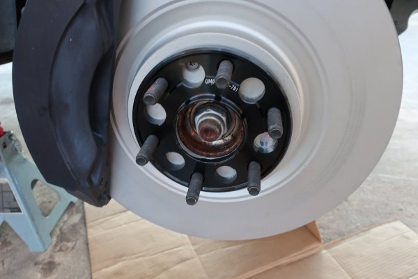
I purchased 15mm thick hub centric spacers for this. They fit perfectly. Only mod I did was to put a thin layer of silver antiseize on the rotor side face of each spacer before sliding them onto the lug studs. Granted, the spacers are anodized and the rotors are coated. I still wanted some corrosion protection.
Remember, I grew up in Ohio. Where aluminum wheels had to be beaten off the rotors with a sledge hammer...


2024-02-28 020.JPG
Passenger's side rotor and caliper reinstalled with the new longer wheel studs.


2024-02-28 021.JPG
15mm hub centric wheel spacer installed on passenger's side front rotor.
 
OP
OP
skpyle

skpyle

Full Access Member
Joined
May 15, 2021
Posts
412
Reaction score
1,081
2024-02-28 016.JPG
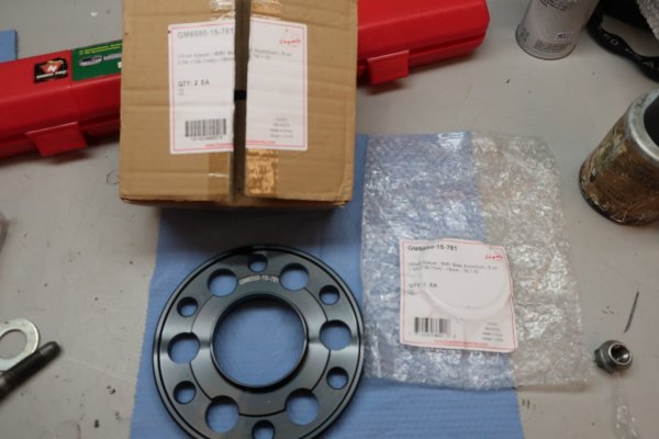
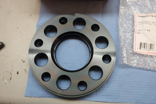
15mm thick hub centric wheel spacers with 6 on 5.5" pattern. I purchased them on Amazon. They are forged and have good review. We shall see...
This shows the wheel side of the spacer.


2024-02-28 019.JPG
This is the rotor side of the spacer.


I have only found 1 'issue' with these wheel spacers. The hub centric ring on the wheel side of the spacer is a light interference it into the back of my wheels. Meaning, when I remove the wheel, the spacer comes with it. This is not really a problem, as there are slots cast into the mounting face inside the wheel. I can get screwdrivers into those slots and gently lever the spacer out of the wheel.


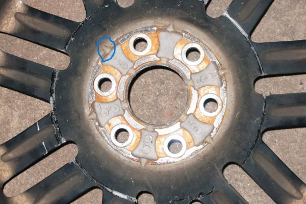
2024-02-15 079.1.JPG
Back side of wheel showing mounting face. Blue circle is one of the slots I put a screwdriver in to lever out the wheel spacer.


I installed the wheels onto the new lug studs and spacers with a thin layer of silver antiseize on the wheel mounting pads and new lug nuts.
The new lug nuts were just because.


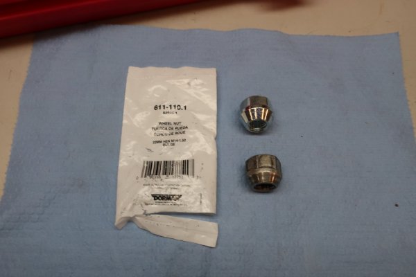
2024-02-28 015.JPG
Dorman 611-110.1 OEM style replacement M14x2.0 lug nut at top, original lug nut at bottom.


2024-02-28 022.JPG
Wheels finally installed with new longer lug studs, spacers, and new lug nuts. Look closely, you can see the wheel spacer hub centric ring in the center bore of the wheel.
 
OP
OP
skpyle

skpyle

Full Access Member
Joined
May 15, 2021
Posts
412
Reaction score
1,081
2024-02-28 023.JPG
16" rotor and Brembo caliper do a nice job of filling up the 22" wheel.


With the front end finally back together, I took my Escalade out for a test drive and to bed the new pads. Drive went well, all felt fine. I bedded in the front brake pads to the rotors using Power Stop's procedure:
-5 aggressive stops from 40mph to 10mph without stopping
-5 moderate stops from 35mph to 5 mph without stopping
-drive home, using the brakes as little as possible, and not coming to a complete stop with the brakes
-let brakes cool

The next morning, I checked torque on the front wheel lug nuts. They all needed a little more to reach 140 lbs/ft.


Having driven my Escalade on this new front brake set-up for 4 days and 175 miles, I have found no faults or issues. I was concerned at increasing the front wheel track by 30mm. There has been no rubbing of the front tires.


2024-02-29 001.JPG
The ball joint separator tool suffered. The forcing screw threads are badly damaged. And the ball at the end of the screw really dug into the tongue of the tool. I am going to need to replace this.

I should have just used the stack of washers and lug nut to pull all the new lug studs in.


2024-02-29 003.JPG
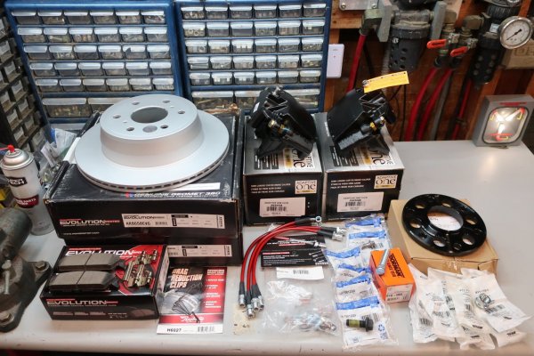
I am now getting set up to rebuild the rear brakes.
New:
-rotors
-complete reman calipers and mounting bolts
-pads and hardware
-pad drag reduction clips
-braided steel brake hoses
-banjo bolts
-longer lug studs
-15mm hub centric wheel spacers
-lug nuts
 
Last edited:
OP
OP
skpyle

skpyle

Full Access Member
Joined
May 15, 2021
Posts
412
Reaction score
1,081
2024-02-29 002.JPG
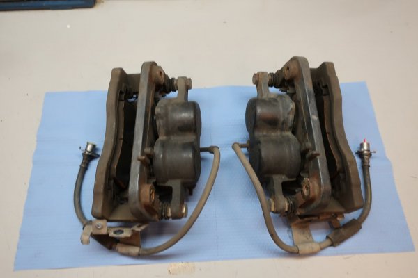
The stock 2-piston floating calipers, brackets, and pads are all in excellent condition.
Do you guys think the GMT800 crowd would be interested in these?

Thanks
 

Forum statistics

Threads
132,301
Posts
1,865,639
Members
96,885
Latest member
BinOdhaib
Top