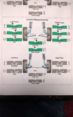
Even though the adjustment cam appears to have more working capacity for adjustment, this does not mean it is allowable for your application. The modified keys increase the distance between the control arms, thereby reducing space for camber correction.
As you can see in the service procedure, there is only 1 way to adjust the values. Just a nut that you loosen for minute changes; lifting the UCA pulls the top of the tire in toward negative camber. With the keys, more distance is created between the U & LCAs so that the LCA doesn't allow for the UCA to come down (and "in") as it was intended with the original eng specs.
With offset UCA bushings, more material of the bushing is placed toward the outside of the vehicle which locates the UCA back toward the inside of the truck, pulling the top of the tire back in toward the vehicle, gaining back some of the 'negative' adjustment capability for camber that was lost.
I know you'd like to think that because the cam shows more correction area, it must be so. If that were the case, companies wouldn't be manufacturing the various sorts of correction equipment. The funky looking ball joints & bushing are marketed for your specific dilemma. Which is to provide an alternate means for providing more negative camber. You don't see this in complete suspension because the front diff drop and longer spindle mimic the OE wheel & driveline geometry.
Only with torsion bar keys do you find this problem with negative camber adjustment difficulty.
Collapse TOC
Search
- Listen
Front Caster and Camber Adjustment
Front Caster and Camber Adjustment
NOTE
Important
Caster measurements or valves must be compensated for the measured frame angle.
Caster is relative to frame, the caster values must be compensated for the measured frame angle by using a digital protractor or equivalent on a flat portion of the frame in front of the rear tire.
Click to Enlarge
Frame angle is positive when higher in the rear. Measure both sides of the frame and take an average from those measurements. Then add the average frame angle to the caster reading when making adjustments.
Click to Enlarge
Frame angle is negative when lower in the rear. Measure both sides of the frame and take an average from the measurements. Then subtract the average frame angle from the caster reading when making adjustments.
- The caster and camber adjustments are made by rotating the offset cam bolt and the cam in the slotted frame bracket in order to reposition the control arm.
NOTE
Important
Before adjusting the caster and camber angles, jounce the front bumper three times to allow the vehicle to return to normal height.
Measure and adjust the caster and the camber with the vehicle at curb height. The front suspension Z dimension is indicated in Trim Heights. Refer to Trim Height Inspection in Suspension General Diagnosis.
For an accurate reading, do not push or pull on the tires during the alignment process.
Click to Enlarge
Determine the caster angle (2). Be sure to compensate for frame angle where required.
Click to Enlarge
Determine the positive camber (2) or negative camber (3) angle.
- Remove the pinned adjusting cam insert. Do not reinstall the cam insert.
- Loosen the upper control arm cam adjustment bolts.
NOTE
Notice
Refer to Fastener Notice | Fastener Notice | Fastener Notice in Cautions and Notices.
Click to Enlarge
NOTE
Note
While performing a front end alignment it may be noticed that the upper control arm bracket alignment pin is missing. This pin serves as a pilot for the alignment cam when adjusting the front caster and camber.
If the pin is missing, a 1/4 inch dowel rod or a punch can be utilized as a temporary alignment aid to properly center the cam to the bracket, while making adjustments and torquing the control arm nuts.
Adjust the caster and the camber angle by turning the cam bolts until the specifications have been met.
When the adjustments are complete, hold the cam bolt head in order to ensure the cam bolt position does not change while tightening the nut.
Tighten
Tighten the cam nuts to 190 N·m (140 lb ft).
- Verify that the caster and the camber are still within specifications. Wheel Alignment Specifications
When the caster and camber are within specifications, adjust the toe. Wheel Alignment - Steering Wheel Angle and/or Front Toe Adjustment

