Correcting Camber After Lift?

Disclaimer: Links on this page pointing to Amazon, eBay and other sites may include affiliate code. If you click them and make a purchase, we may earn a small commission.

Justinj360

Supporting Member
Joined
Jan 2, 2014
Posts
476
Reaction score
85
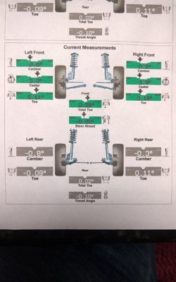
I'm trying to get to the bottom of my camber issue. I've had a 3" torsion key and 2" spacer kit installed on my 2004 Yukon AWD for a while and the tops of my front tires have always been visibly pointed out like this: \\--o--//

It's not drastic but my front tires wear noticeably on the outsides too. I have it aligned regularly and they must be using the stock specs for the alignment? It still has some room for camber adjustment if you look at the bolts and brackets. I'm not an alignment expert but can't they compensate for that some more?

I also talked to the shop that does my alignments and they said to find the lift kit's alignment specs. So I spoke with Rough Country and they said really nothing can be done further... That can't be right... Right?
 

06JET

Full Access Member
Joined
Apr 18, 2018
Posts
169
Reaction score
179
Location
Wisconsin
You need to take it to a different shop. The machine should be seeing the actual wheel position.
 
OP
OP
Justinj360

Justinj360

Supporting Member
Joined
Jan 2, 2014
Posts
476
Reaction score
85
That's exactly what I thought. But after multiple alignments done by 2 different shops over the past 3 or 4 years with this kit installed the camber always comes out the same. Except when I installed the lift kit and when I changed ball joints, those times I know the camber was adjusted.

The camber reading on the print out they give me is just barely in the green zone. Its at least 3 degrees though.

I don't know how the alignment machines work but if the vehicle is aligned in the air would that throw off the camber for a vehicle with a lift when its placed on the ground?
 
OP
OP
Justinj360

Justinj360

Supporting Member
Joined
Jan 2, 2014
Posts
476
Reaction score
85
And the shop I just had it done at was Firestone because I have their lifetime alignment deal.
 
OP
OP
Justinj360

Justinj360

Supporting Member
Joined
Jan 2, 2014
Posts
476
Reaction score
85
Whoops, looks like I was thinking of the 3 degrees for the caster.
How can the camber read almost 0 degrees but the arrow is pointing way to the side?

WP_20180711_17_25_09_Panorama.jpg
 

Chubbs

Full Access Member
Joined
Jun 24, 2017
Posts
634
Reaction score
391
If nobody can do anything with it, you probably have the torsion bar keys cranked up too much. Come down on those suckers about an inch and save your tires, bro ski.

You haven't grenaded the CV axles & upper BJs yet? If you really need the keys maxed out, you can switch over to the degreed upper ball joint or install the modified control arm bushings.

I remember the noticeable camber when I installed some leveling keys to literally "level" it and fit a set of nice Cooper AT 275/65/20 that I scored on CraigsList. I knew I wasn't going to do anything drastic with the TB keys because I had read where people have alignment issues and have to resort to alternative components.

Just that little bit of lift drastically pushed the top of the tires out. I had to go directly to the alignment garage. I couldn't imagine the tech being able to correct double what I had going on at the time.

Aren't you they guy I was talking corvette-spec'd servos with not too long ago?
 
OP
OP
Justinj360

Justinj360

Supporting Member
Joined
Jan 2, 2014
Posts
476
Reaction score
85
If nobody can do anything with it, you probably have the torsion bar keys cranked up too much. Come down on those suckers about an inch and save your tires, bro ski.

You haven't grenaded the CV axles & upper BJs yet? If you really need the keys maxed out, you can switch over to the degreed upper ball joint or install the modified control arm bushings.

I remember the noticeable camber when I installed some leveling keys to literally "level" it and fit a set of nice Cooper AT 275/65/20 that I scored on CraigsList. I knew I wasn't going to do anything drastic with the TB keys because I had read where people have alignment issues and have to resort to alternative components.

Just that little bit of lift drastically pushed the top of the tires out. I had to go directly to the alignment garage. I couldn't imagine the tech being able to correct double what I had going on at the time.

Aren't you they guy I was talking corvette-spec'd servos with not too long ago?

That's what I don't understand, it seems like something can be done with it because the camber brackets aren't maxed out yet. I don't see how 3" is too much for the front... The keys aren't maxed out either.

I just had an inspection at the same time of the alignment and they pointed out that the CV axles wobbled while spinning. They put it on the lift and ran it and you could see the CV axles kind of vibrating. Does that mean anything? I don't know much about them. Those are about the only things I haven't replaced lately.

What do you mean by you had to go directly to the alignment garage? Did you get it figured out?

Yeah that was me with the servo. Did you ever install one?
 
OP
OP
Justinj360

Justinj360

Supporting Member
Joined
Jan 2, 2014
Posts
476
Reaction score
85
That looks like there's plenty of adjustment left to me. They're all about like that. How hard is it to adjust the camber? Is it a pain in the ass and they're just skipping it?
WP_20180712_12_07_12_Panorama.jpg 20180710_235308717_iOS.jpg
 
OP
OP
Justinj360

Justinj360

Supporting Member
Joined
Jan 2, 2014
Posts
476
Reaction score
85
Correct me if I'm wrong but from my basic understanding of alignments, they put in what vehicle they're working on and the machine brings up the factory alignment specs? Then the tech adjusts the suspension to match those? Since my vehicle isn't noticeably lifted could they just be putting the factory specs in? Can't they do it manually or something?
 

Chubbs

Full Access Member
Joined
Jun 24, 2017
Posts
634
Reaction score
391
Even though the adjustment cam appears to have more working capacity for adjustment, this does not mean it is allowable for your application. The modified keys increase the distance between the control arms, thereby reducing space for camber correction.

As you can see in the service procedure, there is only 1 way to adjust the values. Just a nut that you loosen for minute changes; lifting the UCA pulls the top of the tire in toward negative camber. With the keys, more distance is created between the U & LCAs so that the LCA doesn't allow for the UCA to come down (and "in") as it was intended with the original eng specs.

With offset UCA bushings, more material of the bushing is placed toward the outside of the vehicle which locates the UCA back toward the inside of the truck, pulling the top of the tire back in toward the vehicle, gaining back some of the 'negative' adjustment capability for camber that was lost.

I know you'd like to think that because the cam shows more correction area, it must be so. If that were the case, companies wouldn't be manufacturing the various sorts of correction equipment. The funky looking ball joints & bushing are marketed for your specific dilemma. Which is to provide an alternate means for providing more negative camber. You don't see this in complete suspension because the front diff drop and longer spindle mimic the OE wheel & driveline geometry.

Only with torsion bar keys do you find this problem with negative camber adjustment difficulty.


Collapse TOC
Search
  1. Listen
    Front Caster and Camber Adjustment
    Front Caster and Camber Adjustment


    1. NOTE
      Important

      Caster measurements or valves must be compensated for the measured frame angle.


      Caster is relative to frame, the caster values must be compensated for the measured frame angle by using a digital protractor or equivalent on a flat portion of the frame in front of the rear tire.

    2. 819485.gif


      Click to Enlarge
      Frame angle is positive when higher in the rear. Measure both sides of the frame and take an average from those measurements. Then add the average frame angle to the caster reading when making adjustments.

    3. 819489.gif


      Click to Enlarge
      Frame angle is negative when lower in the rear. Measure both sides of the frame and take an average from the measurements. Then subtract the average frame angle from the caster reading when making adjustments.

    4. The caster and camber adjustments are made by rotating the offset cam bolt and the cam in the slotted frame bracket in order to reposition the control arm.


      NOTE
      Important

      Before adjusting the caster and camber angles, jounce the front bumper three times to allow the vehicle to return to normal height.

      Measure and adjust the caster and the camber with the vehicle at curb height. The front suspension Z dimension is indicated in Trim Heights. Refer to Trim Height Inspection in Suspension General Diagnosis.


      For an accurate reading, do not push or pull on the tires during the alignment process.

    5. 821576.gif


      Click to Enlarge
      Determine the caster angle (2). Be sure to compensate for frame angle where required.

    6. 365809.gif


      Click to Enlarge
      Determine the positive camber (2) or negative camber (3) angle.

    7. Remove the pinned adjusting cam insert. Do not reinstall the cam insert.

    8. Loosen the upper control arm cam adjustment bolts.


      NOTE
      Notice

      Refer to Fastener Notice | Fastener Notice | Fastener Notice in Cautions and Notices.


    9. 376758.gif


      Click to Enlarge


      NOTE
      Note

      While performing a front end alignment it may be noticed that the upper control arm bracket alignment pin is missing. This pin serves as a pilot for the alignment cam when adjusting the front caster and camber.

      If the pin is missing, a 1/4 inch dowel rod or a punch can be utilized as a temporary alignment aid to properly center the cam to the bracket, while making adjustments and torquing the control arm nuts.


      Adjust the caster and the camber angle by turning the cam bolts until the specifications have been met.

      When the adjustments are complete, hold the cam bolt head in order to ensure the cam bolt position does not change while tightening the nut.


      Tighten
      Tighten the cam nuts to 190 N·m (140 lb ft).

    10. Verify that the caster and the camber are still within specifications. Wheel Alignment Specifications

      When the caster and camber are within specifications, adjust the toe. Wheel Alignment - Steering Wheel Angle and/or Front Toe Adjustment
 
Last edited:

Forum statistics

Threads
132,450
Posts
1,868,456
Members
97,152
Latest member
ltcoots
Top