This could very well apply to any GM vehicle using the same DRL Module 42767.
I have messed with this problem for a while. Everyone has there method, and I found most of them are stop gap measures that really cause other issues.
If you pull the DRL relay then other intrument features will drop.
If you pull the DRL Module again other instrument features will stop, i.e no PBrake light.
After studying the schematic from the factory shop manual I found the best/cheapest solution is the cut the relay lane on the DRL module circuit board. The nice think about this is that with a little solder you can reenable the DRL feature.
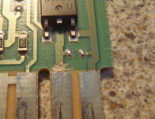
Below is a pic of the mod. The right hand tab of the module were it plugs in, the second from the right most connector is what allows the modele to trip the DRL Relay turning on the head lights. Simple score the pathway just above the silver connector part. You will make to cuts about 2mm apart. Then you want to scrap away the copper material between those two cuts. This breaks the electrical connection just for contacting the DRL relay.
This is simple fix. When you look at your module you will see the pathway. If for somereason you want to reenable the DRL feature, just lightly scrap the connector path so that some copper is exposed and reconnect the two with a little solder. It will not take much and don't go more then 2mm onto the silver part of the connector or it will interfere with the reinsertion of the module.

Attachments
Last edited:


