DYi press in bushings for front control arms?

Disclaimer: Links on this page pointing to Amazon, eBay and other sites may include affiliate code. If you click them and make a purchase, we may earn a small commission.

OneofFew

Full Access Member
Joined
Jun 25, 2018
Posts
240
Reaction score
79
Location
Talullah Falls, Ga
I think I may need bushings up front for my stock height 4x4. They look ok, but I am feeling some wandering when driving. I have a press but no adapters. Has anyone done this that could advise on how hard it is to do?
 

Chubbs

Full Access Member
Joined
Jun 24, 2017
Posts
634
Reaction score
391
That’s 1 hell of a job, bub. These are the procedures required for removing the upper and lower CAs, half of the battle. Once you get them on the bench, I would estimate anywhere from 4-8 hours rebuilding each with new bushing & ball joints.

Nowadays, most folks will buy new control arm assemblies and swap them out as opposed to rebuilding the originals since the cost:benefit isn’t worth the extra time & labor involved.

If you had the cups and presser blanks already on-hand, familiar with the exercise then it might make sense. But if you have never done it before, hours could be spent searching and doing tedious little shit that makes you wish there were new full assemblies sitting in boxes on the floor.

Lower Control Arm Replacement

  • Tools Required
  • J 43631 | J 43631 | J 43631 Ball Joint Separator

  • J 45851 Ball Joint Separator Protector Adapters
Removal Procedure
  1. Raise and support the vehicle. Refer to Lifting and Jacking the Vehicle in General Information.

  2. 160827.gif


    Click to Enlarge
    Support the lower control arm with a safety stand.

  3. Remove the tire and wheel. Refer to Tire and Wheel Removal and Installation in Tires and Wheels.

  4. Remove the stabilizer shaft links from the lower control arm. Refer to Stabilizer Shaft Replacement.

  5. Remove the shock absorber lower nut and the bolt. Refer to Shock Absorber Replacement.

  6. Remove the torsion bars. Refer to Front Torsion Bar Replacement.

  7. Remove the wheel drive shaft. Refer to Wheel Drive Shaft Replacement (2500) in Wheel Drive Shafts.

  8. 830506.gif


    Click to Enlarge
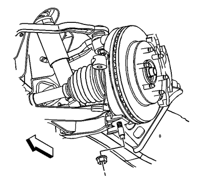
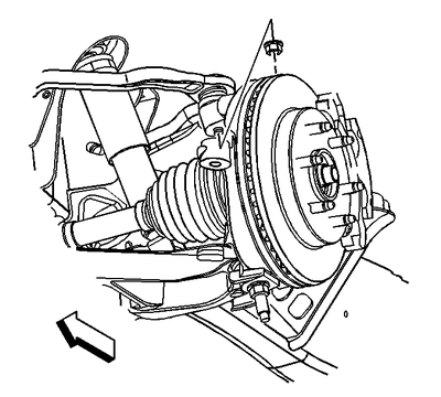
    Remove the lower ball joint retaining nut.

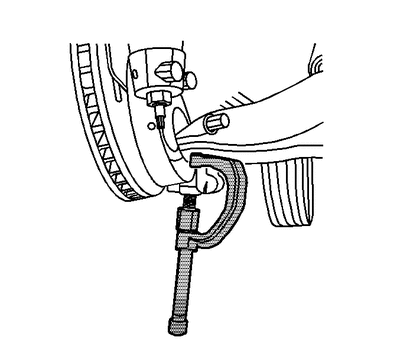
  9. 853943.gif


    Click to Enlarge
    Disconnect the lower ball joint stud from the steering knuckle using J 43631 | J 43631 | J 43631 and J 45851.

  10. 348376.gif


    Click to Enlarge
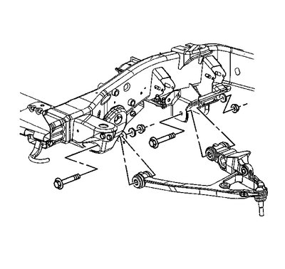
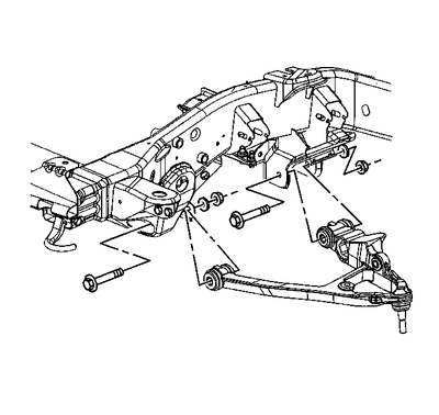
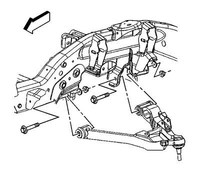
    Remove the lower control arm nuts and the 15-series washers.

  11. Remove the lower control arm bolts.

  12. 348377.gif


    Click to Enlarge
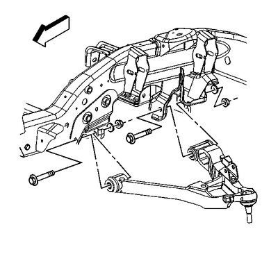
    Remove the lower control arm nuts and the 25/35-series washers.

  13. Remove the lower control arm bolts.

  14. Remove the lower control arm.
Installation Procedure
  1. Install the lower control arm.

  2. 348376.gif


    Click to Enlarge
    Install the lower control arm 15-series bolts.

  3. 348377.gif


    Click to Enlarge
    Install the lower control arm 25/35-series bolts.


  4. NOTE
    Notice

    Refer to Fastener Notice | Fastener Notice | Fastener Notice in Cautions and Notices.


    Install the lower control arm retaining nuts.


    Tighten
    Tighten the nuts to 150 N·m (110 lb ft).

  5. Connect lower ball joint stud to the steering knuckle.

  6. Install the wheel drive shaft. Refer to Wheel Drive Shaft Replacement (2500) in Wheel Drive Shafts.

  7. 830506.gif


    Click to Enlarge
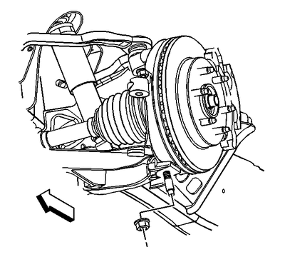
    Install the nut to the lower ball joint stud.


    Tighten
    Tighten the nut to 100 N·m (74 lb ft).

  8. Install the torsion bars. Refer to Front Torsion Bar Replacement.

  9. Install the shock absorber lower nut and bolt. Refer to Shock Absorber Replacement.

  10. Install the stabilizer shaft links to the lower control arm. Refer to Stabilizer Shaft Replacement.

  11. Install the tire and wheel. Refer to Tire and Wheel Removal and Installation in Tires and Wheels.

  12. Remove the safety stands.

  13. Lower the vehicle.

  14. Align the vehicle. Refer to Wheel Alignment Measurement (w/Rear Wheel Steering) | Wheel Alignment Measurement (w/o Rear Wheel Steering) in Wheel Alignment.


Upper Control Arm Replacement
Tools Required

J-42188-B Ball Joint Separator

Removal Procedure
  1. Raise and support the vehicle. Refer to Lifting and Jacking the Vehicle in General Information.

  2. Remove the tire and wheel. Refer to Tire and Wheel Removal and Installation in Tires and Wheels.

  3. Disconnect the electronic suspension control (ESC) link rod from the sensor, if equipped. Refer to Electronic Suspension Front Position Sensor Link Assembly Replacement in Electronic Suspension Control.

  4. 367084.gif


    Click to Enlarge
    Remove the retaining bolt for the brake hose and the wheel speed sensor brackets.

  5. 830521.gif


    Click to Enlarge
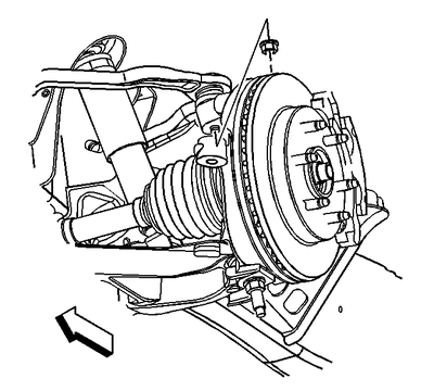
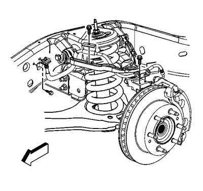
    Remove the upper ball joint retaining nut. Discard the nut.

  6. 1809906.gif


    Click to Enlarge
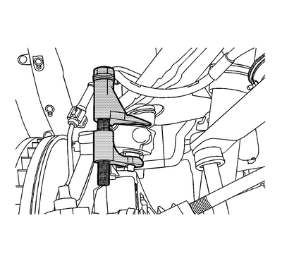
    Disconnect the upper control arm from the steering knuckle using the J-42188-B.

  7. 376754.gif


    Click to Enlarge
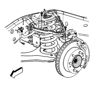
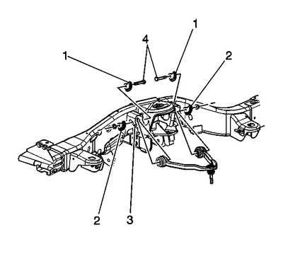
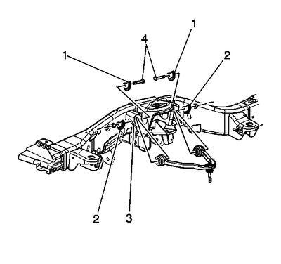
    Remove the upper control arm nuts and the adjustment cams (2) for the 15 Series 2WD, 4WD, and 25/35 Series 2WD.

  8. Remove the upper control arm bolts (4) for the 15 Series 2WD, 4WD, and 25/35 Series 2WD.

  9. 376756.gif


    Click to Enlarge
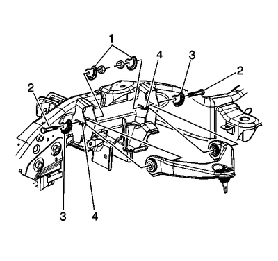
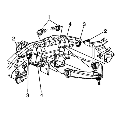
    Remove the upper control arm nuts and the adjustment cams (2) for the 25/35 Series 4WD.

  10. Remove the upper control arm bolts (4) for the 25/35 Series 4WD.

  11. Remove the upper control arm.
Installation Procedure
  1. Install the upper control arm.

  2. 376756.gif


    Click to Enlarge
    Install the upper control arm bolts (4) for the 25/35 Series 4WD.


  3. NOTE
    Notice

    Refer to Fastener Notice in Cautions and Notices.


    Install the upper control arm nuts and the adjustment cams (2) 25/35 Series 4WD.


    Tighten
    Tighten the nuts to 190 N·m (140 lb ft).

  4. 376754.gif


    Click to Enlarge
    Install the upper control arm bolts (4) for the 15 Series 2WD, 4WD, and 25/35 Series 2WD.

  5. Install the upper control arm nuts and the adjustment cams (2) for the 15 Series 2WD, 4WD, and 25/35 Series 2WD.


    Tighten
    Tighten the nuts to 190 N·m (140 lb ft).

  6. Connect the upper control arm to the steering knuckle .

  7. 830521.gif


    Click to Enlarge
    Install the new nut to the upper ball joint stud.


    Tighten
    Tighten the nut to 50 N·m (37 lb ft).

  8. 367084.gif


    Click to Enlarge
    Install the retaining bolts for the brake hose and wheel speed sensor brackets.


    Tighten
    Tighten the bolts to 9 N·m (80 lb in).

  9. Connect the ESC link rod to the sensor, if equipped. Refer to Electronic Suspension Front Position Sensor Link Assembly Replacement in Electronic Suspension Control.

  10. Install the tire and wheel. Refer to Tire and Wheel Removal and Installation in Tires and Wheels.

  11. Remove the safety stands.

  12. Lower the vehicle.

  13. Verify the wheel alignment. Refer to Wheel Alignment Measurement (w/Rear Wheel Steering) | Wheel Alignment Measurement (w/o Rear Wheel Steering) in Wheel Alignment
 

Chubbs

Full Access Member
Joined
Jun 24, 2017
Posts
634
Reaction score
391
Don’t remove and replace, or rebuild & replace without installing new ball joints as well. All of that work just for new bushings, then neglect the ball joints REGARDLESS of condition, is a major FAIL.

These components really need to be in a bad way for warranting such an undertaking. I’m usually the driver of the prevent maint bandwagon but front control arms isn’t for the faint of heart and you certainly need a large assortment of tools, stands, jacks, even more so to rebuild any components. You can get away with much less for a direct remove & replace.
 
Last edited:
OP
OP
OneofFew

OneofFew

Full Access Member
Joined
Jun 25, 2018
Posts
240
Reaction score
79
Location
Talullah Falls, Ga
Great info and input. I am pretty well equipped, but this is major work for sure... The upper looks easier than the lower. I'm gonna try and verify the bad bushings before going through the expense and pita for swapping a pile of heavy metal.
 

Erickk120

Full Access Member
Joined
Mar 19, 2018
Posts
384
Reaction score
214
Just replace the whole control arm. Your truck will thank you
Jesus Christ! I did my upper bushings not too long ago, and its a pity to remove the old rusted ones off! That is putting it lightly, To remove even with a press requires some adjustment abd creativity, They wont straight up fit into it to remove. I had to use my press in reverse to make it work, I used a combination of bearing races I had laying around that matched the the bushing diameter, to remove and install, Installing is the easy part, its removing that will make you regret not just buy the control arm and ball joint already assembled. For the top ones, I would recommend just buy the whole arm, for the bottom that can be pricey, that will be a pain I can imagine, but might be worth it since you save some shekels.
 

Forum statistics

Threads
132,732
Posts
1,873,340
Members
97,563
Latest member
bmead21
Top