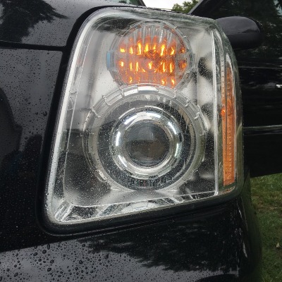
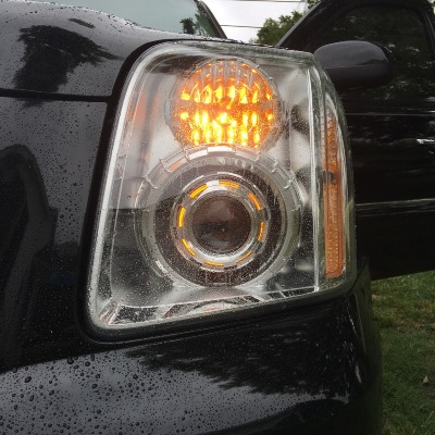
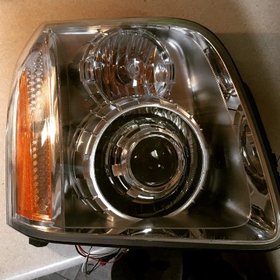
5/20 Edit: Switchback wiring, DRL bypass update, resealing housings, headlight aiming, etc. See a few posts below. TIA!
Okay guys, I've been working on a retro for my wife's '08 Denali this week. Along the way I have tried to document the process and important steps in hopes that it could help someone else down the line. This write up is not quite as detailed as I would like but I have been working on this all while juggling my 1.5yr old son around as well. Some pieces that may be missing were done while multi-tasking. If there is a step that is unclear, or missing, and you have questions, please feel free to ask. I will answer them the best I know how.
Projectors: Morimoto Mini D2S
Shroud: Apollo 3.0
LED: 110mm switchback LED's
Bulbs: Morimoto 4300K D2S
1) Make an OEM headlight adjustment reference
I parked my wife's truck in the driveway about 20-25 front from our garage door. If possible, find a flat surface to park the truck and make this reference. I used paint to make the center of the front tire on the edge of the drive in the grass in case I had to move it for some reason. I also noted where the OEM beams "cutoff" on the garage door. This height and separation measurement will be useful to get your new retrofit pretty close to where they should be aimed in the final step.
(Sorry, I forgot to take a picture of this process)
2) Remove OEM headlights from truck
There are plenty of threads here, and online, on how to remove these headlights. Some may find steps here "unnecessary" to them but this is the easiest way I have found to remove them without damaging any of the fender, bumper, or upper grill.
Pretty basic tools here: 10mm socket, ratchet, 7mm socket.
# of bolts I removed: x7 10mm bolts, x8 7mm bolts.
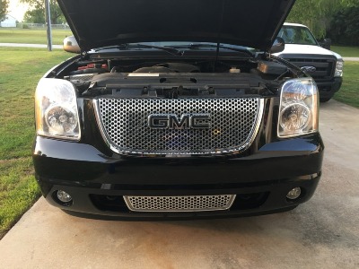
Start by removing the 10mm bolts along the top of the upper grill and upper headlight tabs. I sat these bolts inside the tray behind the driver headlight in order to keep up with them.
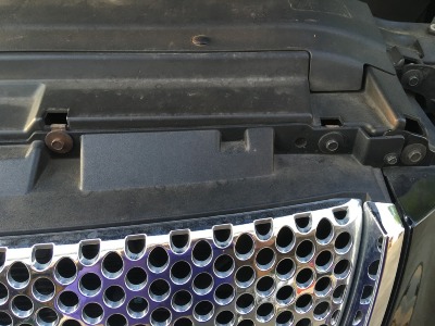
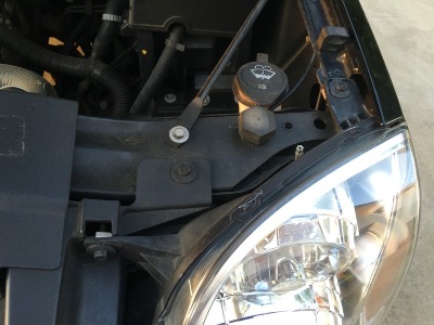
Next, look at the fender liner of the front wheels. In front of the tire, attaching the fender liner to the front bumper, you will see x4 7mm bolts per side. Remove these bolts to gain access to the bottom most 10mm bolt holding the headlight in place:
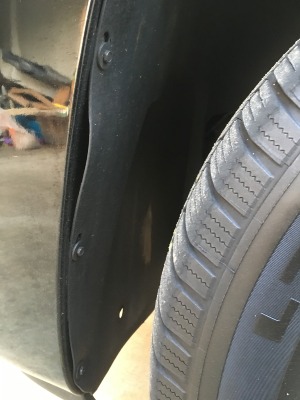
Once those are out, "peel" the fender liner back and look behind the fender. There is x1 10mm bolt back there that has to be loosened. You do not HAVE to remove this bolt if you do not want to. That call is up to you. Should look like so:
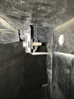
Once that bolt has been loosened, wiggle the headlight free from the bucket. Watch where it makes contact with the inside of the bumper/grill assembly along with the edge of the fender. Take your time here. I pulled the grill assembly out from the car a bit, freed that side of the headlight and removed it that way. One tab at the fender will take some patience to get it to clear the corner there but it will come free. Once almost free, unplug black and grey harness plugs to headlight to free it completely from the truck.
3) Prep and bake the headlights
To prep, remove the OEM headlight bulb, turn signal bulb and park light. Remove the harness for the park light and turn signal as well. Remove rubber "housing cap" that is around the OEM bulb holder. Keep all of this stuff (outside of OEM headlight bulb) as you will reuse it later. Also, remove the x2 T15 bolts from the back of the housing near the outside parking light prior to baking.
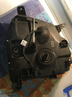
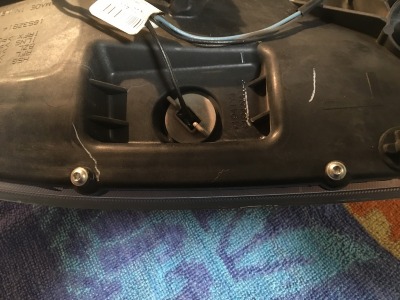
Now, in doing research for this project, all I heard was how hard it was to open OEM housings. I decided to try it before spending $180+ on a set of DEPO's (said to use butyl and be the easiest to open). This step was surprisingly easy for me. Not sure if it's because I have done a few of these over the years or what. I managed to get mine right open after one cycle in the oven.
I baked mine @ 285* for 10 minutes. I preheated the oven WITHOUT the metal rack in it. Once hot, I placed the rack back in and the headlight (face up) on it. Be careful not to allow the headlight to touch anything else in the oven outside of the rack.
(don't judge my dirty oven!!!)
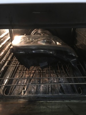
Use pot holders to remove the headlight and rack. Set them in separate places. Keep oven ON in case you have to heat for another cycle.
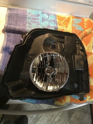
I used a smaller flat head screwdriver to wiggle around the housing seal. I loosened the "locks" on the little bumps all the way around the headlight then started getting it between the lens and back housing and prying it free. I got to a point where I could grab a corner and pull it apart with my hands. Be careful not to let the "glue" string on the inside of the headlight when you pull it apart.
Set the lens off to the side and you should be left with this:
4) Retrofit
Once you have headlight like above picture, remove the x1 T15 bolt to remove the OEM bulb "cover" on the reflector bowl.
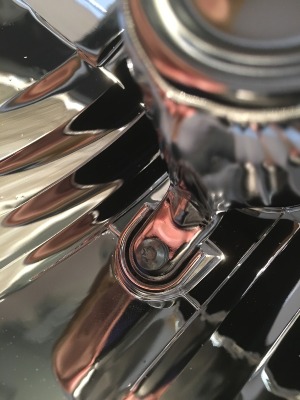
When you flip the headlight over, you will notice that the OEM bulb holder is too deep for the projector to clear. You will have to modify this part by sanding it down as well as making the opening wider. I used the lock nut for the projector as reference for size:
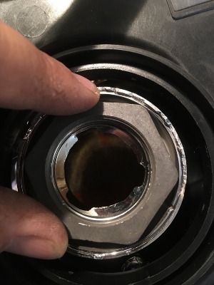
Use your projector to gauge how far down to sand the OEM bulb holder. You will also have to sand the outer ring in order to have access to the lock nut down the road. I used a Dremel tool with a sanding disk and cut off sanding wheel to make this part happen:
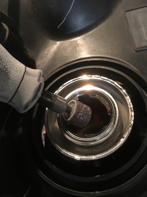
I widened the hole first. I worked a little at a time and kept checking with the threaded neck of the projector until it will clear the opening. After that, I switched to the cutoff wheel to trim down the depth of the bulb holder and outer ring. Final product looked like so:
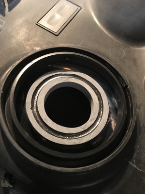
You want those surfaces as even and smooth as possible. This gives a uniform surface for the lock nut to hold onto.
BE CAREFUL NOT TO SAND AND CUT OFF TOO DEEP OR WIDEN OPENING TOO WIDE!!!! Too deep and you get into the back of the OEM reflector bowl...too wide and you will lose that OEM bulb opening to the reflector and you will be S.O.L. at that point!!!!
Test fit the projector and make sure you have enough clearance and depth for the lock nut to tighten down. Install order from reflector bowl side is projector->silicone washer->through headlight->lock nut. Once you are clear, check clearance with bulb and igniter. I had to keep working a bit to get the lock nut "deep" enough to allow room for igniter to be able to lock onto the bulb. Be careful here as well as I have snapped off the bulb "nipples" before during this step. If there is a bit of resistance, either try and tighten the nut more or sand the bottom of the igniter base to clear.
Eye ball the horizontal alignment on the projector if all fits well. You will confirm and adjust this later to where it will be at install back on truck.
5) Installing switchback LED's into backside/inside of Apollo 3.0 shrouds.
I sat the LED rings in the shrouds and make a Sharpie mark on either side of the mounting bumps on the rings. Make them wider than the bump if you are using wire to mount like I did.
Drill these holes using a 3/64" (~1mm) bit and I used 20GA wire from Hobby Lobby:
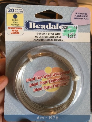
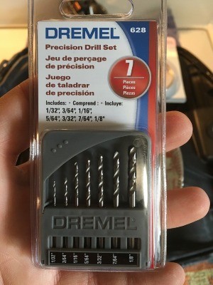
There were x6 holes, x2 per mounting bump location, on each shroud. Insert the wire into the holes from the outside of the projector in. Take each lead and make a tight, 1 pass, loop around the LED ring. Trim off excess not to interfere with projector. Here is the instructions from the site:
XSB Halo 2.0 Switchback Install Instructions
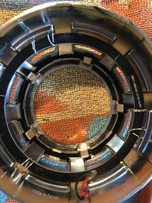
Once LED's are secured, onto routing wiring
6) Route highbeam solenoid control wires and LED wires
I drilled a 5/32 hole just below the T15 OEM bulb cover bolt through the front of the projector and out the back of the housing. Plug the solenoid control up and route those through the hole and out the back of the headlight. Unpin the red and black wires on the LED control and route those out the back as well. Test the highbeam solenoid on a 9V battery using BRN = - and WHT = +. If all is well, install those wires in the supplied 9005/6 style plug and this will plug directly into the harness.
I have yet to get to the LED wiring. Seems as if you will have constant 12V+, ground and the orange goes to the turn signal lead on the truck. I gather if you do not wish to use the amber turn signal function, you can leave this lead off and it will be fine.
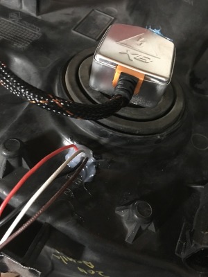
Where the hole for those wires comes out the back of the housing, I put some clear silicone to prevent moisture in the headlights:
7) Install and route harness.
You have a lead to the battery + and ground, a ground for each ballast input, MotoControl box mounting, ballast mounting, harness to ballast and igniter to ballast. On my truck, with only one battery, I tapped into the passenger side headlight plug and did NOT have anything that will go to the driver side headlight plug. This part I will leave up to you as there is no concrete way to mount and route this. The harness is labeled so its pretty easy.
8) Check horizontal alignment of projectors and functionality of all wiring
Install headlights prior to sealing them back up. Make all connections. Look in engine bay fuse box and remove 15A fuses for DRL and DRL2. I THINK the #s are 30 & 32. There is a diagram on the inside of the lid that will direct you to which fuses to pull.
Rotate projectors as needed and tighten lock nut on back to secure. Once your satisfied, install shrouds.
9) Seal lights
Back in the oven at 285* for 10 min to reheat OEM glue, out and press the lens and rear housing together. I purchased the butyl from TRS so I will be doing that to ensure a good seal.
Seal light, install, make connections, ENJOY!
Okay guys, I've been working on a retro for my wife's '08 Denali this week. Along the way I have tried to document the process and important steps in hopes that it could help someone else down the line. This write up is not quite as detailed as I would like but I have been working on this all while juggling my 1.5yr old son around as well. Some pieces that may be missing were done while multi-tasking. If there is a step that is unclear, or missing, and you have questions, please feel free to ask. I will answer them the best I know how.
Projectors: Morimoto Mini D2S
Shroud: Apollo 3.0
LED: 110mm switchback LED's
Bulbs: Morimoto 4300K D2S
1) Make an OEM headlight adjustment reference
I parked my wife's truck in the driveway about 20-25 front from our garage door. If possible, find a flat surface to park the truck and make this reference. I used paint to make the center of the front tire on the edge of the drive in the grass in case I had to move it for some reason. I also noted where the OEM beams "cutoff" on the garage door. This height and separation measurement will be useful to get your new retrofit pretty close to where they should be aimed in the final step.
(Sorry, I forgot to take a picture of this process)
2) Remove OEM headlights from truck
There are plenty of threads here, and online, on how to remove these headlights. Some may find steps here "unnecessary" to them but this is the easiest way I have found to remove them without damaging any of the fender, bumper, or upper grill.
Pretty basic tools here: 10mm socket, ratchet, 7mm socket.
# of bolts I removed: x7 10mm bolts, x8 7mm bolts.

Start by removing the 10mm bolts along the top of the upper grill and upper headlight tabs. I sat these bolts inside the tray behind the driver headlight in order to keep up with them.


Next, look at the fender liner of the front wheels. In front of the tire, attaching the fender liner to the front bumper, you will see x4 7mm bolts per side. Remove these bolts to gain access to the bottom most 10mm bolt holding the headlight in place:

Once those are out, "peel" the fender liner back and look behind the fender. There is x1 10mm bolt back there that has to be loosened. You do not HAVE to remove this bolt if you do not want to. That call is up to you. Should look like so:

Once that bolt has been loosened, wiggle the headlight free from the bucket. Watch where it makes contact with the inside of the bumper/grill assembly along with the edge of the fender. Take your time here. I pulled the grill assembly out from the car a bit, freed that side of the headlight and removed it that way. One tab at the fender will take some patience to get it to clear the corner there but it will come free. Once almost free, unplug black and grey harness plugs to headlight to free it completely from the truck.
3) Prep and bake the headlights
To prep, remove the OEM headlight bulb, turn signal bulb and park light. Remove the harness for the park light and turn signal as well. Remove rubber "housing cap" that is around the OEM bulb holder. Keep all of this stuff (outside of OEM headlight bulb) as you will reuse it later. Also, remove the x2 T15 bolts from the back of the housing near the outside parking light prior to baking.


Now, in doing research for this project, all I heard was how hard it was to open OEM housings. I decided to try it before spending $180+ on a set of DEPO's (said to use butyl and be the easiest to open). This step was surprisingly easy for me. Not sure if it's because I have done a few of these over the years or what. I managed to get mine right open after one cycle in the oven.
I baked mine @ 285* for 10 minutes. I preheated the oven WITHOUT the metal rack in it. Once hot, I placed the rack back in and the headlight (face up) on it. Be careful not to allow the headlight to touch anything else in the oven outside of the rack.
(don't judge my dirty oven!!!)

Use pot holders to remove the headlight and rack. Set them in separate places. Keep oven ON in case you have to heat for another cycle.
I used a smaller flat head screwdriver to wiggle around the housing seal. I loosened the "locks" on the little bumps all the way around the headlight then started getting it between the lens and back housing and prying it free. I got to a point where I could grab a corner and pull it apart with my hands. Be careful not to let the "glue" string on the inside of the headlight when you pull it apart.
Set the lens off to the side and you should be left with this:

4) Retrofit
Once you have headlight like above picture, remove the x1 T15 bolt to remove the OEM bulb "cover" on the reflector bowl.

When you flip the headlight over, you will notice that the OEM bulb holder is too deep for the projector to clear. You will have to modify this part by sanding it down as well as making the opening wider. I used the lock nut for the projector as reference for size:

Use your projector to gauge how far down to sand the OEM bulb holder. You will also have to sand the outer ring in order to have access to the lock nut down the road. I used a Dremel tool with a sanding disk and cut off sanding wheel to make this part happen:

I widened the hole first. I worked a little at a time and kept checking with the threaded neck of the projector until it will clear the opening. After that, I switched to the cutoff wheel to trim down the depth of the bulb holder and outer ring. Final product looked like so:

You want those surfaces as even and smooth as possible. This gives a uniform surface for the lock nut to hold onto.
BE CAREFUL NOT TO SAND AND CUT OFF TOO DEEP OR WIDEN OPENING TOO WIDE!!!! Too deep and you get into the back of the OEM reflector bowl...too wide and you will lose that OEM bulb opening to the reflector and you will be S.O.L. at that point!!!!
Test fit the projector and make sure you have enough clearance and depth for the lock nut to tighten down. Install order from reflector bowl side is projector->silicone washer->through headlight->lock nut. Once you are clear, check clearance with bulb and igniter. I had to keep working a bit to get the lock nut "deep" enough to allow room for igniter to be able to lock onto the bulb. Be careful here as well as I have snapped off the bulb "nipples" before during this step. If there is a bit of resistance, either try and tighten the nut more or sand the bottom of the igniter base to clear.
Eye ball the horizontal alignment on the projector if all fits well. You will confirm and adjust this later to where it will be at install back on truck.
5) Installing switchback LED's into backside/inside of Apollo 3.0 shrouds.
I sat the LED rings in the shrouds and make a Sharpie mark on either side of the mounting bumps on the rings. Make them wider than the bump if you are using wire to mount like I did.
Drill these holes using a 3/64" (~1mm) bit and I used 20GA wire from Hobby Lobby:


There were x6 holes, x2 per mounting bump location, on each shroud. Insert the wire into the holes from the outside of the projector in. Take each lead and make a tight, 1 pass, loop around the LED ring. Trim off excess not to interfere with projector. Here is the instructions from the site:
XSB Halo 2.0 Switchback Install Instructions

Once LED's are secured, onto routing wiring
6) Route highbeam solenoid control wires and LED wires
I drilled a 5/32 hole just below the T15 OEM bulb cover bolt through the front of the projector and out the back of the housing. Plug the solenoid control up and route those through the hole and out the back of the headlight. Unpin the red and black wires on the LED control and route those out the back as well. Test the highbeam solenoid on a 9V battery using BRN = - and WHT = +. If all is well, install those wires in the supplied 9005/6 style plug and this will plug directly into the harness.
I have yet to get to the LED wiring. Seems as if you will have constant 12V+, ground and the orange goes to the turn signal lead on the truck. I gather if you do not wish to use the amber turn signal function, you can leave this lead off and it will be fine.
Where the hole for those wires comes out the back of the housing, I put some clear silicone to prevent moisture in the headlights:

7) Install and route harness.
You have a lead to the battery + and ground, a ground for each ballast input, MotoControl box mounting, ballast mounting, harness to ballast and igniter to ballast. On my truck, with only one battery, I tapped into the passenger side headlight plug and did NOT have anything that will go to the driver side headlight plug. This part I will leave up to you as there is no concrete way to mount and route this. The harness is labeled so its pretty easy.
8) Check horizontal alignment of projectors and functionality of all wiring
Install headlights prior to sealing them back up. Make all connections. Look in engine bay fuse box and remove 15A fuses for DRL and DRL2. I THINK the #s are 30 & 32. There is a diagram on the inside of the lid that will direct you to which fuses to pull.
Rotate projectors as needed and tighten lock nut on back to secure. Once your satisfied, install shrouds.
9) Seal lights
Back in the oven at 285* for 10 min to reheat OEM glue, out and press the lens and rear housing together. I purchased the butyl from TRS so I will be doing that to ensure a good seal.
Seal light, install, make connections, ENJOY!
Last edited:

