So I want to first off thank Wade (01Konvict) for creating this amazing thread and thank you to all the others who posted. I am posting my first hand experience in regards to lifting an autoride vehicle...
Vehicle- 07 Tahoe LTZ
Lift- 3.5" Rough Country
After scouring the internet for many moons on ways to get the ride height I wanted, I decided on the 3.5" RC lift kit. I didn't want to go 6"+ or get a "leveling" kit I was looking for the height in between. I contemplated doing a level + body lift, but from what I have read, body lifts are no bueno. Even the shop I got my lift installed at recommended against it.
On to the details of what I had to do for my particular set up....
Wheels- Fuel Ripper 20x9 +1 offset
Tires- Toyo M/T 295/60/20 (the Toyos are slightly skinnier and a tad taller than most 295/60/20s)
Additional parts purchased- FTS Autoride extension adapters, 1/4" wheel spacers (rear)
So long short if you are wondering if you need to buy shock extenders along with the RC 3.5" lift, the answer is no. I did purchase extra parts JUST in case. The last thing you want is to have a shop tear your car apart, just to realize you need additional parts. I also purchased a full set of 1" wheel spacers, but ended up not needing them as my stance was perfect at about 1" outside the fender
Now the bad... arriving at the shop a little early to pick up my car, I wanted to check it out while it was up in the air and see if there were any issues and how everything looked
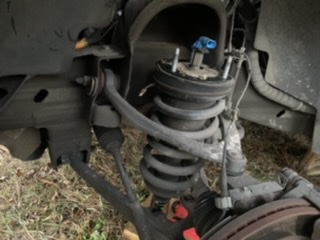
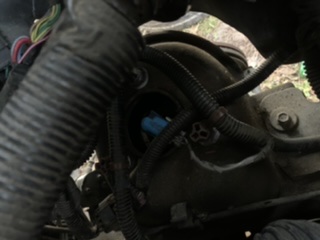
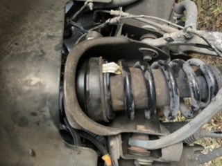
1) Front Auto Dampening- Well I didn't even know I had this feature on my car, but hopefully this helps out the next person. I can't say that if your car has autoride that is has auto dampening struts, but I imagine it does. On the very top of your front struts there is a female connector that comes out at a 45 degree angle. With the RC lift spacer on, this connector isn't able to connect to the male piece, there simply not enough space in the strut cut inside the engine bay to make it work. I tried sanding the female connector down to right before the interior terminals, but that did not work, I still needed about 1/2 an inch to clear. Using some audio equipment I had on hand, I cut the male connecter off to leave enough room to splice the wires. I used some speaker connectors I had and clamped them on the spliced wires, making sure to mark the correct input on the female piece (I also used the rubber "sleeves" to mark negative and positive.) After doing so, they slide right on the terminals then clamped it on the top of the strut.
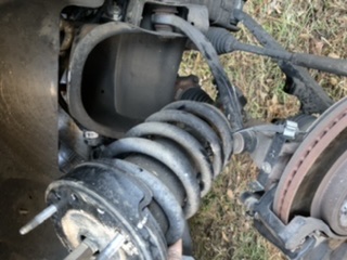
2) Front Autoride/Auto Dampening Extension- As mentioned above, I was not aware that I had this feature. I was ready to get everything straightened out as I am a very impatient person and a perfectionist. Along with how this thread was started, I needed to extend my front autoride sensor. The FTS extensions were running about $100 with shipping, PLUS I would have to wait on them. So I took the advice of another member in this thread and purchased 10x24 threaded rods from Lowe's. Cost a few bucks and having the adjustable FTS extensions on the rear definitely helped with getting everything on point. When removing the autoride ride. I simply jacked the vechicle on one side to relieve the tension, sprayed WD-40 on the end caps and slid them off. It's a pain in the butt to unscrew them from the top and bottom and I think they were designed to do as I did. I unscrewed the rubber caps from the end using 2 clamping pliers. I ended up cutting the 10x24 rod to 5" exactly for each side and adjusted the rear to 1/2" from rod end piece to extension on BOTH sides of the rod.
3) Trimming- I knew there would be some trimming involved as the RC lift says you can run up to a 33". Well I wasn't settling for that, thats why I went with the 295/60 as these come out to be approx 34.4" x 11.8". Basically you suck in the width so you can go taller and get the rim offset to match around +-5. Had to trim a good bit in the back of the front fender, including the running board. But I'm ok with it as the Hoe looks amazing!
Been driving for about a week now and it has thrown ZERO codes and rides just like stock, which is why I wanted to keep the autoride in the first place. I have a Diablo Progammer on hand to diagnose codes just in case.
Pics to come!


