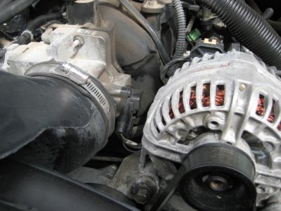
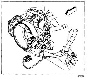
If you have a "drive by wire" TB then just remove the air duct and clean the TB and blade with a quality choke cleaner and a soft tooth brush.
Removing the IAC is not necessary.
The condition is caused by dirt build up on the TB bore and blade
Increased Accelerator Pedal Effort, Idle Instability (Clean Throttle Body and Adjust Blade) #02-06-04-054B - (03/17/2003)
Table 1: TPS Voltage Chart
Increased Accelerator Pedal Effort, Idle Instability (Clean Throttle Body and Adjust Blade)
1999-2002 Chevrolet Silverado
2000-2002 Chevrolet Suburban, Tahoe
2002 Chevrolet Avalanche
1999-2002 GMC Sierra
2000-2002 GMC Yukon, Yukon XL
with 4.8L or 5.3L V8 Engine (VINs V, T, Z -- RPOs LR4, LM7, L59)
This bulletin is being revised to add condition information. Please discard Corporate Bulletin Number 02-06-04-054A (Section 06-Engine).
Condition
Some customers may comment on an idle instability and/or a higher than expected accelerator pedal effort from the idle position.
Cause
Condition may be caused by deposits in the throttle body bore and on the throttle plate.
Correction
Important
This procedure only applies to cable actuated throttle bodies on the models listed above. This procedure should not be performed on electronically controlled throttle bodies or on any vehicle or engine that is not listed above in the Models section.
Verify that the cause for this condition is not a damaged or binding throttle cable.
Remove the air intake duct. Refer to Air Cleaner Duct Replacement.
Inspect the vehicle for installation of a fixed orifice PCV valve, refer to Corporate Bulletin Number 01-06-01-029B for PCV valve identification. Vehicles undergoing this throttle body procedure MUST use a Fixed Orifice PCV Valve, P/N 12572717.
Clean throttle body bore and throttle valve plate of carbon using a shop rag and an appropriate cleaner. Refer to Engine Controls Repair Procedures - Throttle Body Cleaning Procedure.
Select the correct plug for the size of the air bypass hole in the throttle body being serviced. Use a 1/8-inch (.125") drill bit to determine which plug to use.
Vehicles built before introduction of the Fixed Orifice PCV Valve will have a 3.75 mm (.150") air bypass hole in the throttle plate. The 1/8-inch drill bit is smaller than the air bypass hole in these throttle bodies and can be inserted into the bypass hole. To plug the air bypass hole in these vehicles requires the yellow plug, P/N 12580749.
Vehicles built after introduction of the Fixed Orifice PCV Valve will have a 2.6 mm (.104") air bypass hole in the throttle plate. The 1/8-inch drill bit is larger than the air bypass hole in these throttle bodies and cannot be inserted into the bypass hole. To plug the air bypass hole in these vehicles requires the red plug, P/N 12581011.
Insert the appropriate plug (1) into the air bypass hole in the throttle plate. Insert the "tail" end of the plug through the throttle plate air bypass hole.
Open the throttle plate to allow access to the tail end of the plug. Pull the tail section to securely position the plug into the air bypass hole and trim excess material (1) from plug.
Turn ignition key to the on position, with engine off.
Use the Tech 2 Scan tool to read initial TPS voltage.
Important
TPS voltage cannot exceed .69 V. If the vehicle has an initial TPS voltage greater than .61 V, replace the Throttle Body Assembly. This part is currently on parts restriction. Contact the General Motors Powertrain Quality Center at 866-654-7654 for assistance.
Using the Tech 2 Scan tool and a T15 driver to rotate the Minimum Air Rate screw, increase TPS voltage by .08 Volts (Refer to TPS Voltage Chart below).
Turn ignition key to the off position. Verify that the accelerator pedal moves freely - Depress the accelerator pedal to the floor and release.
Install the air intake duct. Refer to Air Cleaner Duct Replacement.
Start engine.
Using the Tech 2 scan tool, monitor TPS voltage and verify the TPS voltage is no greater than 0.69V.
Road Test Vehicle.
Important
If an increased accelerator pedal effort condition still exists after performing this bulletin, throttle body replacement may be required. Please contact the General Motors Powertrain Quality Center at 866-654-7654 for assistance, as the throttle body is currently on a parts restriction program.
TPS Voltage Chart Initial TPS Voltage
TPS Voltage After .08 Volt Increase
0.45 V
0.53 V
0.47 V
0.55 V
0.49 V
0.57 V
0.51V
0.59 V
0.53 V
0.61 V
0.55 V
0.63 V
0.57 V
0.65 V
0.59 V
0.67 V
0.61 V
0.69 V
If initial TPS voltage is greater than .61 V Replace Throttle Body Assembly
Parts Information
Part Number
Description
Qty
12580749
Plug, Throttle Plate - Yellow
1
12581011
Plug, Throttle Plate - Red
1
Parts are currently available from GMSPO.


