Alex_M
Full Access Member
- Joined
- Sep 27, 2021
- Posts
- 376
- Reaction score
- 678
Hey all! So you've lost your key, and the dealer cut key didn't work. Or maybe someone tried to steal your truck and buggered up the ignition cylinder. I found myself in both of these situations in the past week, in two separate vehicles. Here's my solution.
Let me go ahead and state, you will have to disable or bypass the passlock system for this to work. In my Tahoe I already had the VATS disabled VIA HPTuners. The resistor bypass should also work, but may take more figuring.
Let it be known that your truck will no longer take a key to start, unless you use a keyed switch in place of one of the toggle switches. Now, on to the write up.
This is not a super thorough write up, but there is plenty of info here for a competent person to complete the job. Pin out information is provided.
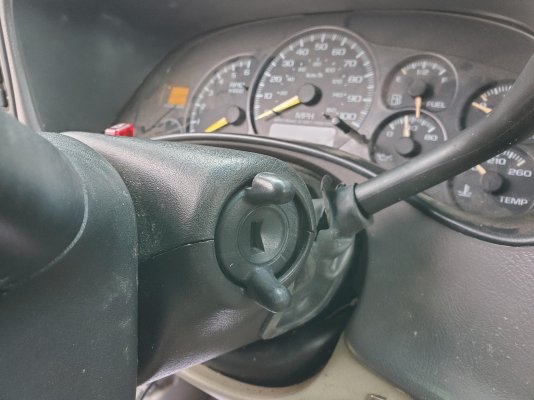
Of course you'll have to begin by removing the plastic cover from your steering column. Once that is out of the way you will take a chisel and a hammer and remove the ignition cylinder and housing. It is possible to remove them without destroying the housing, but it requires removal of the steering wheel and I never intend to go back to a keyed ignition. IF YOU DO WANT TO RETURN TO A KEYED IGNITION, DO NOT BUST OFF THE HOUSING. The housing alone is currently about $130 from the dealer, and the ignition cylinder is another $75.
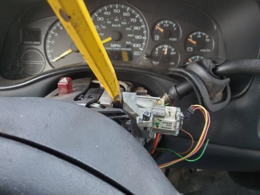
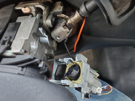
Now take a screwdriver and pop the ignition switch out of the housing.
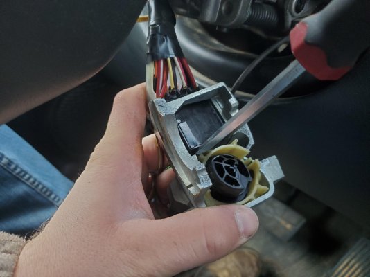
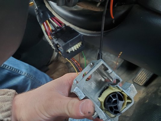
At this point, if you're in a pinch and just trying to get home, you can roll the wheel by hand and then bridge pins 1 and 2 to start your vehicle. Again, the passlock will have to be either tuned out or bypassed with a resistor. Pin out is shown below, all pins are numbered.
If you intend to comete the conversion, take a pair of ***** and cut all the wires free. Strip them all back enough to twist the correct pairs together.
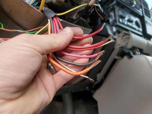
Here is the pin out.
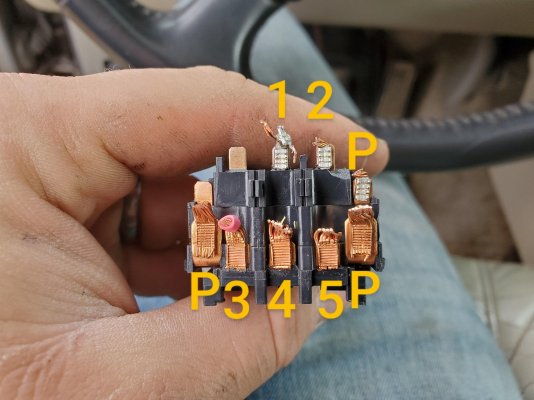
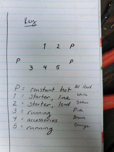
As you can see from the pin out, your pairs are as follows.
Orange and Pink
Brown and White, plus starter button feed
The three reds are all constant hot. Make jumpers to extend your wires far enough to reach where your switches are going to go. I highly recommend solder and heat shrink, or at the very least use heat shrink crimp connectors. I used stranded #12 THHN wire that I had laying around. That is rated for a 20a load, same as most toggle switches.
At this point, be sure to also solder in a pair of wires for the starter button. One wire should go in with the load side of one of your switches. I chose the accessories switch for easy cranking without firing if I need that capability in the future. Possibly helpful for compression tests or priming the oiling system when necessary. The other will connect back to the yellow wire, Pin 2.
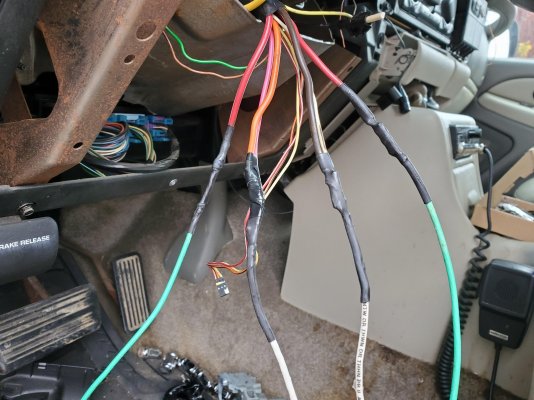
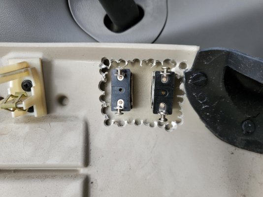
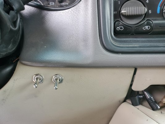
I decided to mount my toggle switches in the knee panel beside where the factory ignition switch was. This panel is double layered, so you will need to drill your hole for the switch and then trim a layer off the back side for the switches to recess into. This would be cleaner to use a Dremel or oscillating tool, but I had a drill within reach and this will not be seen.
I used two switches to my accessories and ignition are separate. I am not sure what the amp draw is on these wires, but you may have to use two in order to maintain safety. The largest of the factory wires is actually a #10 and there are two separate primary power feeds, so that leads me to believe there may be decent draw on the system.
I soldered one feed (line side) to each switch, and then my accessories load to one and ignition load to the other.
Ignore the burnt insulation. I soldered these all using propane. I'd recommend a soldering gun instead, but I used what I had handy. If you use propane, be careful. It is VERY easy to overheat and ruin the switches. Remember the very tip of the internal cone of the flame is the hottest point and will allow the quickest soldering.
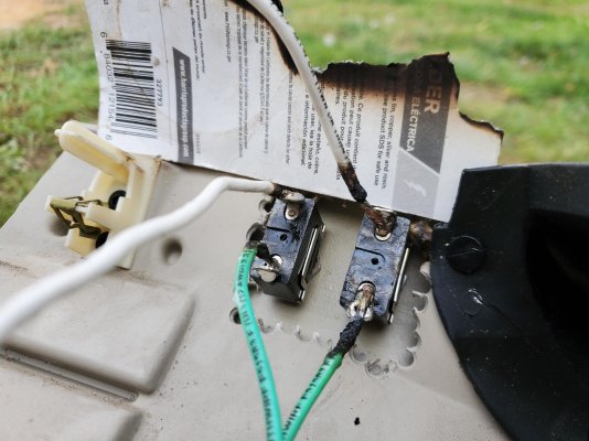
At this point I decided to use some black tape to bundle the wires to keep them tidy, and I reinstalled this knee panel.
I fed my starter button wires up and around my instrument cluster to reach the location I chose for it.
For this you will need a momentary switch. I got a nice little stainless steel momentary switch from Amazon and decided to mount it above my instrument cluster. Easily reached by grasping the dash and reaching under with my thumb, but not completely in plain sight.
This switch will not do anything unless the accessories switch is on in my setup because no power is being fed to it otherwise. If only the accessories are on it will crank, but will not fire. This gives a small amount of security requiring both switches to be on in order for the truck to start.
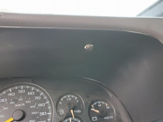
In order for it to be able to be mounted in this location I did have to trim a piece of the dash out, but this is covered back over by the dash bezel and will never be seen.
These connections were also soldered.
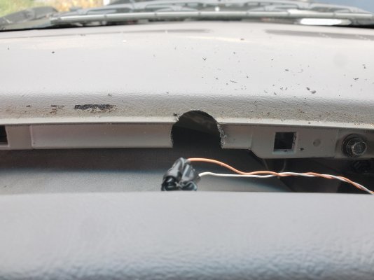
And here is the final mounted location of my switches.
Now! It appears I forgot to photograph this last part, but you have to disable the steering wheel lock. The lock is just a steel pin that is pushed back out of place when the ignition is turned. It is at the top of the round milled spot on the right hand side of the column.
I just pushed it back and held it out of the way with a screwdriver, then drilled a hole thru the top of the column and sent a screw down through the hole to act as a retaining pin. I did not go through the pin itself; I intersected the shelf that is cut into the pin. Very simple solution that you won't have to worry about.
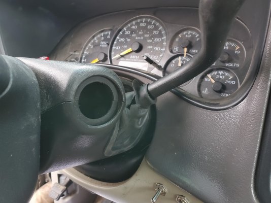
And finally I reassembled the plastic cover for the steering column. With the ignition housing removed the top piece does not have anywhere to bolt. This is not a problem. When the two halves of the clam shell snap together, the bottom piece mounts to the column and holds the top piece in place solidly.
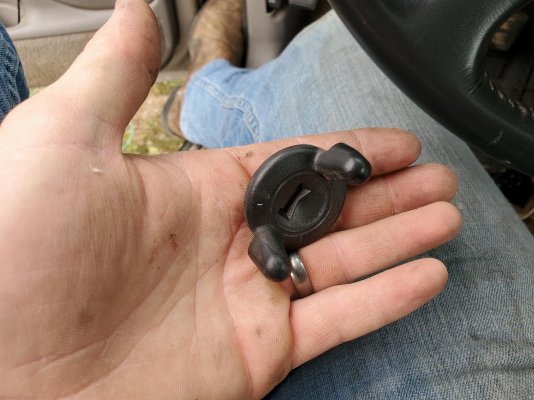
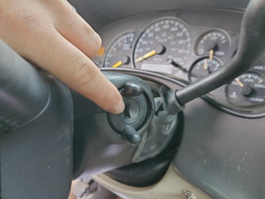
Now with the open hole left, I broke the cover off the old ignition and simply used some super glue to mount it back in place.
If you wanted to, it would be very simple to cut a piece of black plastic and mount your starter button here instead, but I preferred the alternative location.
Let me go ahead and state, you will have to disable or bypass the passlock system for this to work. In my Tahoe I already had the VATS disabled VIA HPTuners. The resistor bypass should also work, but may take more figuring.
Let it be known that your truck will no longer take a key to start, unless you use a keyed switch in place of one of the toggle switches. Now, on to the write up.
This is not a super thorough write up, but there is plenty of info here for a competent person to complete the job. Pin out information is provided.
Of course you'll have to begin by removing the plastic cover from your steering column. Once that is out of the way you will take a chisel and a hammer and remove the ignition cylinder and housing. It is possible to remove them without destroying the housing, but it requires removal of the steering wheel and I never intend to go back to a keyed ignition. IF YOU DO WANT TO RETURN TO A KEYED IGNITION, DO NOT BUST OFF THE HOUSING. The housing alone is currently about $130 from the dealer, and the ignition cylinder is another $75.


Now take a screwdriver and pop the ignition switch out of the housing.


At this point, if you're in a pinch and just trying to get home, you can roll the wheel by hand and then bridge pins 1 and 2 to start your vehicle. Again, the passlock will have to be either tuned out or bypassed with a resistor. Pin out is shown below, all pins are numbered.
If you intend to comete the conversion, take a pair of ***** and cut all the wires free. Strip them all back enough to twist the correct pairs together.

Here is the pin out.


As you can see from the pin out, your pairs are as follows.
Orange and Pink
Brown and White, plus starter button feed
The three reds are all constant hot. Make jumpers to extend your wires far enough to reach where your switches are going to go. I highly recommend solder and heat shrink, or at the very least use heat shrink crimp connectors. I used stranded #12 THHN wire that I had laying around. That is rated for a 20a load, same as most toggle switches.
At this point, be sure to also solder in a pair of wires for the starter button. One wire should go in with the load side of one of your switches. I chose the accessories switch for easy cranking without firing if I need that capability in the future. Possibly helpful for compression tests or priming the oiling system when necessary. The other will connect back to the yellow wire, Pin 2.

I decided to mount my toggle switches in the knee panel beside where the factory ignition switch was. This panel is double layered, so you will need to drill your hole for the switch and then trim a layer off the back side for the switches to recess into. This would be cleaner to use a Dremel or oscillating tool, but I had a drill within reach and this will not be seen.
I used two switches to my accessories and ignition are separate. I am not sure what the amp draw is on these wires, but you may have to use two in order to maintain safety. The largest of the factory wires is actually a #10 and there are two separate primary power feeds, so that leads me to believe there may be decent draw on the system.
I soldered one feed (line side) to each switch, and then my accessories load to one and ignition load to the other.
Ignore the burnt insulation. I soldered these all using propane. I'd recommend a soldering gun instead, but I used what I had handy. If you use propane, be careful. It is VERY easy to overheat and ruin the switches. Remember the very tip of the internal cone of the flame is the hottest point and will allow the quickest soldering.


At this point I decided to use some black tape to bundle the wires to keep them tidy, and I reinstalled this knee panel.
I fed my starter button wires up and around my instrument cluster to reach the location I chose for it.
For this you will need a momentary switch. I got a nice little stainless steel momentary switch from Amazon and decided to mount it above my instrument cluster. Easily reached by grasping the dash and reaching under with my thumb, but not completely in plain sight.
This switch will not do anything unless the accessories switch is on in my setup because no power is being fed to it otherwise. If only the accessories are on it will crank, but will not fire. This gives a small amount of security requiring both switches to be on in order for the truck to start.

In order for it to be able to be mounted in this location I did have to trim a piece of the dash out, but this is covered back over by the dash bezel and will never be seen.
These connections were also soldered.

And here is the final mounted location of my switches.

Now! It appears I forgot to photograph this last part, but you have to disable the steering wheel lock. The lock is just a steel pin that is pushed back out of place when the ignition is turned. It is at the top of the round milled spot on the right hand side of the column.
I just pushed it back and held it out of the way with a screwdriver, then drilled a hole thru the top of the column and sent a screw down through the hole to act as a retaining pin. I did not go through the pin itself; I intersected the shelf that is cut into the pin. Very simple solution that you won't have to worry about.
And finally I reassembled the plastic cover for the steering column. With the ignition housing removed the top piece does not have anywhere to bolt. This is not a problem. When the two halves of the clam shell snap together, the bottom piece mounts to the column and holds the top piece in place solidly.
Now with the open hole left, I broke the cover off the old ignition and simply used some super glue to mount it back in place.
If you wanted to, it would be very simple to cut a piece of black plastic and mount your starter button here instead, but I preferred the alternative location.


