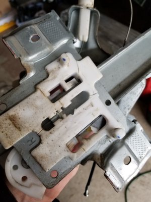
B3205 0B
I dont even know where to start.
From the shop manual:
Diagnostic Aids
B3205 0B can be set due to excessive physical resistance in the window regulator assembly. Ensure proper mechanical operation of the regulator assembly prior to replacing electrical components.
Reference Information
Schematic Reference
Moveable Window Schematics (See: Windows and Glass\Windows\Diagrams\Electrical)
Connector End View Reference
Component Connector End Views (See: Diagrams\Connector Views)
Description and Operation
Power Windows Description and Operation (See: Windows and Glass\Windows\Description and Operation\Power Windows Description and Operation)
Electrical Information Reference
Circuit Testing (See: Testing and Inspection\Component Tests and General Diagnostics)
Connector Repairs (See: Testing and Inspection\Component Tests and General Diagnostics)
Testing for Intermittent Conditions and Poor Connections (See: Testing and Inspection\Component Tests and General Diagnostics)
Wiring Repairs (See: Testing and Inspection\Component Tests and General Diagnostics)
Scan Tool Reference
Control Module References (See: Testing and Inspection\Programming and Relearning) for scan tool information
Circuit/System Verification
Observe the operation of the power windows while commanding each window UP and DOWN by using their respective window switches, each window should perform the UP and DOWN function.
Circuit/System Testing
Ignition OFF, disconnect the harness connector at the appropriate window motor.
Connect a test lamp between control circuit terminal A and control circuit terminal B.
Ignition ON, command the window UP and DOWN by using the door switch. The test lamp should turn ON when commanding the UP and DOWN states.
¤ If the test lamp is always OFF during either of the commands, test either control circuit for a short to ground or open/high resistance. If the circuits test normal, replace the door switch.
¤ If the test lamp is always ON, test either control circuit for a short to voltage. If the circuits test normal, replace the door switch
If all circuits test normal, test or replace the window motor.
Component Testing
Important: When performing the following tests, make sure that the window motor is not all ready in the position the test is attempting to produce.
Ignition OFF, disconnect the harness connector at the appropriate window motor.
Install a 25A fused jumper wire between the control terminal A and 12 volts. Momentarily install a jumper wire between the control terminal B and ground. The window motor should perform the UP or DOWN function.
¤ If the function does not perform as specified, replace the window motor.
Reverse the jumper wires; the window motor should perform the DOWN or UP function.
¤ If the function does not perform as specified, replace the window motor

