Need some help - 1997 Tahoe Heater / Blower Motor

Disclaimer: Links on this page pointing to Amazon, eBay and other sites may include affiliate code. If you click them and make a purchase, we may earn a small commission.
Mean_Green

Full Access Member
Joined
Mar 23, 2023
Posts
415
Reaction score
542
Connector shells arrived. As expected, I had to break part of the old shell since two of the pins were partially melted in place. Once removed, they looked OK though, no metal distortion from heat that I could see. Slipped into the new shell OK, all but one that I had to fight a bit for some reason. Blue bars snapped back in OK.

I was going to abandon the actuator motor until I found I could get one 'free'. Decided to try again to get it out. Had to break the far back, hidden mounting post, but it's out. Glued that post back in place to help support the new one. Strength not a major factor since no screw will be put back in. Not fighting that.

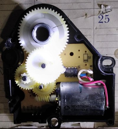
Opened it up and yes, the main gear is split.

ActOpen.jpg

I still don't understand how it's supposed to work though. Plugging it in and watching it, the metal center hub stops, but the motor continues to run driving the gear around the hub. If I press the Recirc button, the motor reverses, driving the hub until it stops, but the motor and gear keep running. Press the button again, the same thing happens.

No matter which way it goes, I don't see what's supposed to tell the motor to turn off. Is it just resistance? Is there something in that chip that senses the motor can't turn any more and kills power?
 

east302

Full Access Member
Joined
Dec 21, 2016
Posts
1,630
Reaction score
1,516
Location
Mississippi
Good question, I had wondered the same. I’ve read that the actuator uses a potentiometer, but don’t really know how that works. Does that help?
 

Mean_Green

Full Access Member
Joined
Mar 23, 2023
Posts
415
Reaction score
542
No pot. Two 1/2 watt fixed resistors, two diodes, two caps and that one chip. Nothing around the metal hub to sense position either way.

Chip is marked Motorola 0372DP1 CKVN 9736 which seems to be some sort of Op Amp.
 

Mean_Green

Full Access Member
Joined
Mar 23, 2023
Posts
415
Reaction score
542
Any timers/counters on that board? pretty simple for motor pole counter. X revolutions signal change. would expect to see a trim pot though.
I don't see anything. If I knew for sure which pins were G, V+ and V-, I'd try to run it on the bench and see what happens.
Does the blower work at all speeds now?
New control should be here Friday.
 

Mean_Green

Full Access Member
Joined
Mar 23, 2023
Posts
415
Reaction score
542
Hard to see in my picture with the shadowing, but the pins on the board are marked 5, 6 & 7.

But their terminology is confusing. 'Signal' is telling me something other than straight 12VDC is being applied and there is something other than a simple polarity reversal. Since the switches inside the control unit appear to be simple push button, lock on, lock off switches, I have to wonder if the PCM is involved somehow.

Where do 454, 1614 and 733 go?

Or maybe I'm just overthinking. I guess what I'm trying to figure out is if I have something else wrong that's just going to eat the new motor and new HVAC control.
 
Last edited:

Forum statistics

Threads
132,748
Posts
1,873,495
Members
97,572
Latest member
707jimenez
Top