ok this has been a Monkey on my back for way to long! I have a 01 Yukon xl slt, 4x4. To make a long story as short as Possible, I had a issue with it wandering since day one 3 1/2 years ago, I replaced both hubs with timkins, (one had a cracked tone ring so I did both) then trying to figure out the drift ( it was intermittent and felt like driving on soft ground) it occasionally went away for a day or so. I rebuilt the entire front end (tie rod ends inner and outer, pitman arm, idler arm and bracket, sway bar bushings, and had a wheel alignment done!) the parts were all Moog! I still had a drift but it was a little better but then there was a noise I thought was possibly a front axle bearing but turned out to be the spider gears in the rear G80, I replaced the entire rear axle with a 80000 mile Boneyard unit ( I opened and inspected closely Refilled with the proper oil) I also replaced all the shocks with new bilsteins the rear was a conversion kit with shocks and new springs to eliminate the Nivomats ( the right rear was bad, now after everything I replaced It still isn’t right so I got a steering stabilizer and it did absolutely nothing! I did check the balljoints they are tight! The dealer that did the alignment confirmed the balljoints were good! Besides a bent or cracked frame that I can’t see what else could be going on? The only thing not stock is the tires they are Firestone Destination at but just a couple sizes up from the stock size nothing that should affect the handling it just raised the Yukon about 1 1/2. Any ideas that I can look into?
You are using an out of date browser. It may not display this or other websites correctly.
You should upgrade or use an alternative browser.
You should upgrade or use an alternative browser.
Steering issues after 90% rebuild?
- Thread starter KR66
- Start date
Disclaimer: Links on this page pointing to Amazon, eBay and other sites may include affiliate code. If you click them and make a purchase, we may earn a small commission.
swathdiver
Full Access Member
Have the tires been on since you rebuilt the front end? How old are they (by date code)?
The tires are new about 3 months old and I rotated them after 4000 Miles.the drift is mild but bad enough that I can’t take my eyes off the road for a seceded to look out a side window for a second or I’m not traveling straight and have to correct the path again, and it’s not a pull it goes either way right or left I can’t feel it it’s too subtleHave the tires been on since you rebuilt the front end? How old are they (by date code)?
M1Gunner
Full Access Member
May need to just snug up the gear box.
I can’t find any play anywhere I had it up on jack stands all 4 off the ground the steering wheel had maybe 1/4” of play I’m hoping it’s not something in the 4x4 system like the transfer case hanging in auto mode? Regardless of what mode it’s in the 4x4 system is quite and seems to go in and out of 2H 4H 4L and Auto without any sign of a problem! When I put it in Auto it seems to handle a little stiffer but I guess that’s because the front axle is engaged waiting for slippage for the clutches in the transfer case to engage . Unless I do have a issue with the front axle? I had a GoPro under it to look for signs of anything visible but nothing! I hate to sell it I have to much time and money into it! The sunroof was just replaced under insurance when a tree limb fell on it and the usaa adjuster was even amazed at how clean it was for a 2001May need to just snug up the gear box.
Chubbs
Full Access Member
- Joined
- Jun 24, 2017
- Posts
- 634
- Reaction score
- 391
What method was used for inspecting/testing the ball joints? It doesn't require a complete failure to affect overall vehicle handling.
Please post your process. A factory authorized or dealer level service tech would use a dial indicator gauge to verify the lateral movement within the ball joint assembly and exactly how much. Anything outside of the specs will result in negative feedback to the steering & chassis, both.
I had another suv 2-years ago that would wander at speeds over 40/50 mph and it was the ball joints failing both times. Don't cheap out on replacement parts when it comes time; it's not an exercise that you want to do, or pay somebody to do, more than once.
If you are really serious about fixing the problem, get a shop manual for your truck and have a go. It has steps and procedure for diagnosing and repair of anything, basically.
Poor Directional Stability
Step Action Yes No
DEFINITION: Driver is unable to maintain consistent, predictable vehicle driving control in any direction.
1
Did you review the General Description and perform the necessary inspections?
Go to Step 2
Go to Symptoms - Suspension General Diagnosis
2
Verify that the directional stability is poor.
Does the system operate normally?
System OK
Go to Step 3
3
Inspect the front stabilizer for the following conditions:
Go to Step 10
Go to Step 4
4
Inspect the following suspension and steering components for wear or damage:
Go to Step 10
Go to Step 5
5
Inspect the wheel bearing. Refer to Wheel Bearings Diagnosis.
Did you find and correct the condition?
Go to Step 10
Go to Step 6
6
Inspect the vehicle trim height. Refer to Trim Height Inspection.
Did you find and correct the condition?
Go to Step 10
Go to Step 7
7
Inspect the steering column for looseness. Refer to Looseness in Steering Column in Steering Wheel and Column.
Did you find and correct the condition?
Go to Step 10
Go to Step 8
8
Inspect the steering gear for the following conditions:
Go to Step 10
Go to Step 9
9
Inspect and adjust the wheel alignment as necessary. Refer to Wheel Alignment Measurement (w/Rear Wheel Steering) | Wheel Alignment Measurement (w/o Rear Wheel Steering) in Wheel Alignment.
Did you complete the alignment?
Go to Step 10
—
10
Operate the vehicle in order to verify the repair.
Did you correct the condition?
System OK
Go to Step 3
Ball Joint Inspection (Lower Ball Joint)
Special Tools
J 8001 Dial Indicator Set
Ball Joint Inspection (Upper Ball Joint)
Tools Required
J 8001 | J 8001 | J 8001 | J 8001 | J 8001 | J 8001 | J 8001 | J 8001 Dial Indicator Set
Please post your process. A factory authorized or dealer level service tech would use a dial indicator gauge to verify the lateral movement within the ball joint assembly and exactly how much. Anything outside of the specs will result in negative feedback to the steering & chassis, both.
I had another suv 2-years ago that would wander at speeds over 40/50 mph and it was the ball joints failing both times. Don't cheap out on replacement parts when it comes time; it's not an exercise that you want to do, or pay somebody to do, more than once.
If you are really serious about fixing the problem, get a shop manual for your truck and have a go. It has steps and procedure for diagnosing and repair of anything, basically.
Poor Directional Stability
Step Action Yes No
DEFINITION: Driver is unable to maintain consistent, predictable vehicle driving control in any direction.
1
Did you review the General Description and perform the necessary inspections?
Go to Step 2
Go to Symptoms - Suspension General Diagnosis
2
Verify that the directional stability is poor.
Does the system operate normally?
System OK
Go to Step 3
3
Inspect the front stabilizer for the following conditions:
- Stabilizer fasteners for looseness
Refer to Fastener Tightening Specificationsin Front Suspension.
- Worn or damaged stabilizer or stabilizer bushings
Refer to Stabilizer Shaft Replacement in Front Suspension.
- Damaged or missing stabilizer links
Refer to Stabilizer Shaft Link Replacement (2500) in Front Suspension.
Go to Step 10
Go to Step 4
4
Inspect the following suspension and steering components for wear or damage:
- Control Arms
Refer to Upper Control Arm Replacement or Lower Control Arm Replacement in Front Suspension.
- Ball Joints
Refer to Ball Joint Inspection (Lower Ball Joint) | Ball Joint Inspection (Upper Ball Joint).
- Tie rod ends
Refer to Tie Rod Replacement in Steering Linkage or Rear Wheel Steering Inner Tie Rod Replacement or Rear Wheel Steering Linkage Outer Tie Rod Replacement in Rear Wheel Steering.
Go to Step 10
Go to Step 5
5
Inspect the wheel bearing. Refer to Wheel Bearings Diagnosis.
Did you find and correct the condition?
Go to Step 10
Go to Step 6
6
Inspect the vehicle trim height. Refer to Trim Height Inspection.
Did you find and correct the condition?
Go to Step 10
Go to Step 7
7
Inspect the steering column for looseness. Refer to Looseness in Steering Column in Steering Wheel and Column.
Did you find and correct the condition?
Go to Step 10
Go to Step 8
8
Inspect the steering gear for the following conditions:
- Steering gear mounting bolts for looseness
Refer to Fastener Tightening Specificationsin Power Steering.
- Pitman shaft over-center adjustment
Refer to Steering Gear Pitman Shaft Over-Center Preload Adjustment - Off Vehicle in Power Steering System.
Go to Step 10
Go to Step 9
9
Inspect and adjust the wheel alignment as necessary. Refer to Wheel Alignment Measurement (w/Rear Wheel Steering) | Wheel Alignment Measurement (w/o Rear Wheel Steering) in Wheel Alignment.
Did you complete the alignment?
Go to Step 10
—
10
Operate the vehicle in order to verify the repair.
Did you correct the condition?
System OK
Go to Step 3
Ball Joint Inspection (Lower Ball Joint)
Special Tools
J 8001 Dial Indicator Set
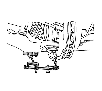
Click to Enlarge- Raise and support the vehicle. Refer to Lifting and Jacking the Vehicle.
- With the wheel and tire on the vehicle, lift the suspension corner by hand to determine if any looseness is present. If vertical free play is experienced proceed with the following instructions.
- Remove the wheel and tire. Refer to Tire and Wheel Removal and Installation.
- Clean and inspect the ball joint seals for cuts or tears. If the ball joint seals are damaged, replace the ball joint. Refer to Lower Control Arm Ball Joint Replacement (Coil Spring Suspension) | Lower Control Arm Ball Joint Replacement (Torsion Bar Suspension).
- Install and position the dial indicator from J 8001 Dial Indicator Set against the end of the ball joint.
NOTE
Important
Do not pry between the lower arm and the wheel drive shaft boot or in such a manner that the ball joint seal is contacted. Damage to the wheel drive shaft boot will result (4WD).
Gently lift or pry the suspension upward then let it settle.
- The dial indicator reading should be no more than 2 mm (0.079 in). If the reading is out of specification, replace the ball joint.
Ball Joint Inspection (Upper Ball Joint)
Tools Required
J 8001 | J 8001 | J 8001 | J 8001 | J 8001 | J 8001 | J 8001 | J 8001 Dial Indicator Set
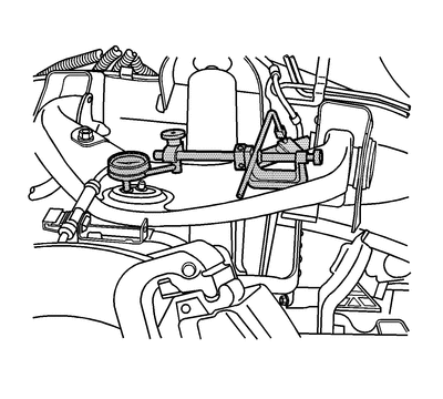
Click to Enlarge- Raise and support the vehicle. Refer to Lifting and Jacking the Vehicle.
- With the wheel and tire on the vehicle, lift the suspension corner by hand to determine if any looseness is present. If vertical free play is experienced proceed with the following instructions.
- Remove the wheel and tire. Refer to Tire and Wheel Removal and Installation.
- Support the lower control arm with a floor stand or jack, as far outboard as possible.
- If a seal is cut or torn, replace the ball joint.
- Clean and inspect the ball joint seals for cuts or tears. If the ball joint seals are damaged, replace the ball joint. Refer to Upper Control Arm Replacement.
- Check the wheel bearing for looseness in the wheel bearing is present. Refer to Wheel Bearings Diagnosis.
- Check the upper ball joint for vertical looseness.
- Remove the lower shock absorber mounting bolt. This will ensure that the suspension is unloaded.
- Install and position the dial indicator from J 8001 | J 8001 | J 8001 | J 8001 | J 8001 | J 8001 | J 8001 | J 8001 against the rim of the upper ball joint.
- Apply downward force to the upper control arm and zero the indicator pointer/pad against the rim of the upper ball joint.
- Release the arm and check the dial indicator. The dial indicator reading should be no more than 2 mm (0.079 in). If the reading is too high, replace the upper control arm. Refer to Upper Control Arm Replacement.
Last edited:
I recently had the steering gear replaced on my '04 Hoe, 99,500 on the clock. The lower ball joints had been replaced earlier this year and at that time the (very trusted) mechanic indicated that there was a bit too much slop in the steering gear and the pitman arm would soon need to be replaced. After the ball joints and alignment it still had the wandering problem, so I went ahead with the pitman arm and steering gear replacement. No more wandering.
There is a thread or two about tightening up the steering gear, and having a competent mechanic do the troubleshooting is a godsend. The guy I use has an Avalanche with over 500K miles on it and it rides and runs perfectly.
There is a thread or two about tightening up the steering gear, and having a competent mechanic do the troubleshooting is a godsend. The guy I use has an Avalanche with over 500K miles on it and it rides and runs perfectly.
I’ll look into that thanksI recently had the steering gear replaced on my '04 Hoe, 99,500 on the clock. The lower ball joints had been replaced earlier this year and at that time the (very trusted) mechanic indicated that there was a bit too much slop in the steering gear and the pitman arm would soon need to be replaced. After the ball joints and alignment it still had the wandering problem, so I went ahead with the pitman arm and steering gear replacement. No more wandering.
There is a thread or two about tightening up the steering gear, and having a competent mechanic do the troubleshooting is a godsend. The guy I use has an Avalanche with over 500K miles on it and it rides and runs perfectly.
I may need to experiment with tire pressure! I know that there’s a lot of debate on what pressure to set tires at, the Yukon says 32 psi with the Stock tire size but the Firestone Destination ATs I have on it are taller and narrower than the stock tire! So the contact patch is smaller! The tire says 44 psi now I remember in Tech school that the pressure difference is due to the amount of sq inches of contact with the road the larger the contact the less pressure is needed to support the load! Vise versa, I have had many say to use the sticker # 32 psi regardless of the tire but I think this is only if it’s the same dimension tire? It does seem to handle better with say 38 psi than 32 psi I’m just afraid of ruining a $900 set to tires running them to high or low, the tread on The Destination AT is semi aggressive I’m going to post a few photos of the tires and specs to this message in a reply I can’t do it with the device I’m using right now
Last edited:
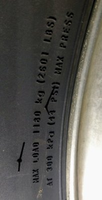
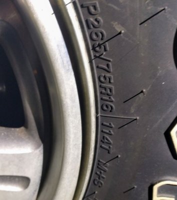
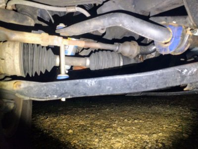
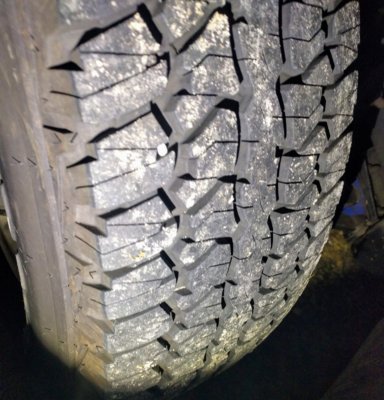
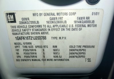


as you can see the factory size is supposed to be a 70 series tire and I have 75 series on it so the tire is a bit skinnier than the stock needing a bit more air to hold the same weight. The tread is little aggressive but not to extreme ( I like it because they stick and handle rain and snow really well! Almost impossible to trigger the abs in a panic stop (on dry pavement) I think they may grab as well as Michelin's) you can see all the new parts underneath it was all replaced between 12/17 and 5/18 (tires, shocks, tie rods, pitman, idler, bushings, Timkin hubs, etc)I may need to experiment with tire pressure! I know that there’s a lot of debate on what pressure to set tires at, the Yukon says 32 psi with the Stock tire size but the Firestone Destination ATs I have on it are taller and narrower than the stock tire! So the contact patch is smaller! The tire says 44 psi now I remember in Tech school that the pressure difference is due to the amount of sq inches of contact with the road the larger the contact the less pressure is needed to support the load! Vise versa, I have had many say to use the sticker # 32 psi regardless of the tire but I think this is only if it’s the same dimension tire? It does seem to handle better with say 38 psi than 32 psi I’m just afraid of ruining a $900 set to tires running them to high or low, the tread on The Destination AT is semi aggressive I’m going to post a few photos of the tires and specs to this message in a reply I can’t do it with the device I’m using right now
Last edited:
Similar threads
- Replies
- 15
- Views
- 3K
