Tahoe DRL Blinker Switchback LED ReWire

Disclaimer: Links on this page pointing to Amazon, eBay and other sites may include affiliate code. If you click them and make a purchase, we may earn a small commission.

90PROFX

Member
Joined
Apr 4, 2016
Posts
35
Reaction score
14
DwebPro,
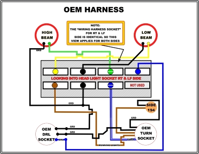
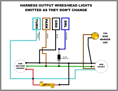
With your help I'd like to detail your mod into an easy to view/understand wiring diagram, as I and another member are a little confused. As an example, I've attached the OEM wiring diagram (color correct) to start with, this diagram is for right & left side head light buckets as the harness's are the same. With your advise and help I'll add a new diagram to reflect all what you've done, cut's splice, diode etc. etc. You'll have to help me out on that as I'm a little lost on what went where in your mod.


NOTE: Head Light Grounds are backwards, see new diagram below
DRL%20PROJECT_OEM_zps95dv26gs.jpg~original
 
Last edited:

Graystone_OG

Full Access Member
Joined
Nov 6, 2013
Posts
161
Reaction score
41
Location
NYC
DwebPro,
With your help I'd like to detail your mod into an easy to view/understand wiring diagram, as I and another member are a little confused. As an example, I've attached the OEM wiring diagram (color correct) to start with, this diagram is for right & left side head light buckets as the harness's are the same. With your advise and help I'll add a new diagram to reflect all what you've done, cut's splice, diode etc. etc. You'll have to help me out on that as I'm a little lost on what went where in your mod.


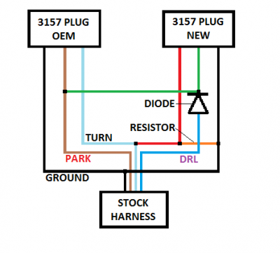
I attached a picture of a diagram I created. It's pretty straight forward. The colors should match up with the stock wiring and the new 3157 plug.

Dual LED Switchback Diagram 2.png
 

90PROFX

Member
Joined
Apr 4, 2016
Posts
35
Reaction score
14
All comments, replies and opinions welcome.

Alright, pardon my ignorance but here is the OEM Harness layout:

OEM%20POST_zpsu8hpsy6x.jpg

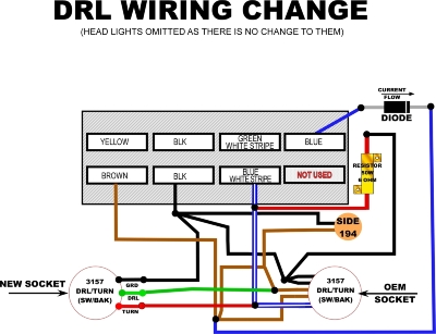
And the way I'm looking at the mod is this wiring harness (change from OEM), correct ???????

DRL%20POST_zpsrgdt1kur.jpg
 
Last edited:

90PROFX

Member
Joined
Apr 4, 2016
Posts
35
Reaction score
14
Graystone,

Thanks for the diagram, I finally had a chance to sit down by myself (in peace and quiet) and study your sketch, it now makes total sense. I think I was getting hung up on all the looping done on the OEM harness. Thanks again.

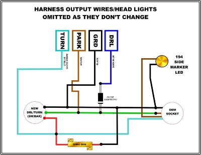
So based on your diagram, this is what I'm understanding the wiring to be, redrawn so I can envision it (for dummies) like me to understand:

Graystone%20Diagram_zpsi9rltsf4.jpg
 
Last edited:

Graystone_OG

Full Access Member
Joined
Nov 6, 2013
Posts
161
Reaction score
41
Location
NYC
Graystone,

Thanks for the diagram, I finally had a chance to sit down by myself (in peace and quiet) and study your sketch, it now makes total sense. I think I was getting hung up on all the looping done on the OEM harness. Thanks again.

So based on your diagram, this is what I'm understanding the wiring to be, redrawn so I can envision it (for dummies) like me to understand:

Graystone%20Diagram_zpsi9rltsf4.jpg

Hey no problem. That's what's great about collaboration and sharing ideas. If no one understands it now, they shouldn't be near anything electric lol.

Sent from my Nexus 6P using Tapatalk
 

Slammed

TYF Newbie
Joined
May 2, 2009
Posts
27
Reaction score
21
Bumping an old thread

really need to do this thanks for the write up

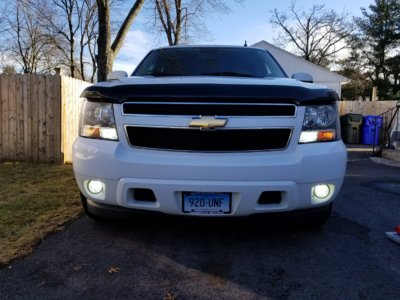
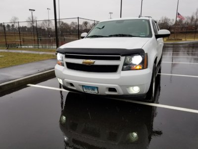
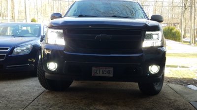
20180212_153713.jpg 20180216_145335.jpg
 

Forum statistics

Threads
132,748
Posts
1,873,506
Members
97,573
Latest member
Roblusk
Top