6L80 Sonnax ZIP Kit, Pressure Switch rebuild, remote filter install, and fluid flush in 2013 Escalade ESV (Pic heavy)

Disclaimer: Links on this page pointing to Amazon, eBay and other sites may include affiliate code. If you click them and make a purchase, we may earn a small commission.

OP
OP
skpyle

skpyle

Full Access Member
Joined
May 15, 2021
Posts
414
Reaction score
1,087
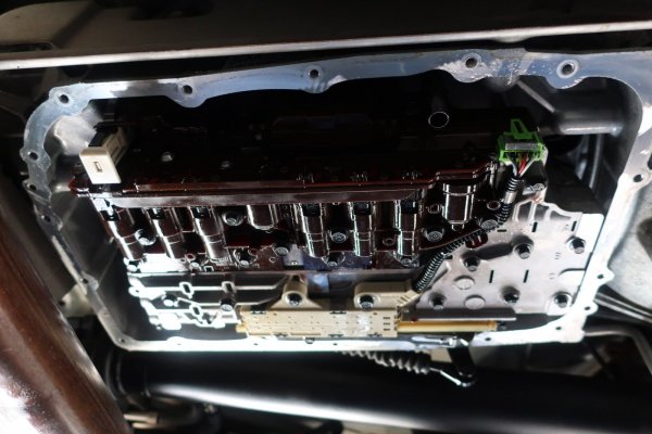
This is one of the main reasons I went through all the effort to pull the valve body out of my 6L80 transmission: to rebuild the pressure switches. Mine worked fine, but I wanted to go ahead and rebuild them preemptively.


2021-10-24 100.JPG
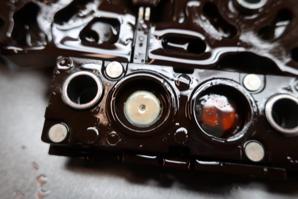
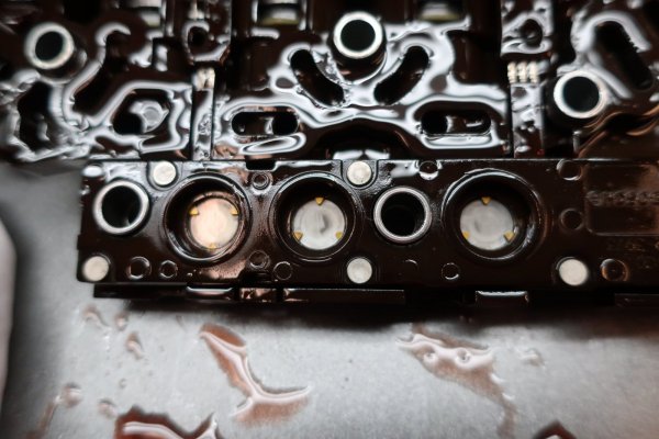
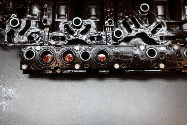
The round port with the sorta orangish center is one of the pressure switches. The outer part is the seal, and the inner part is the disc/diaphragm. The seals and diaphragms are the failure items. Diaphragms more so. From what I understand, the diaphragms break/rip/tear/etc... over time and stop actuating the switch below. Age and dirty ATF add to the wear. In some cases, the seals deteriorate and fail as well.
Note the discolored spot on the disc. This is light sludge from the ATF.


2021-10-24 101.JPG
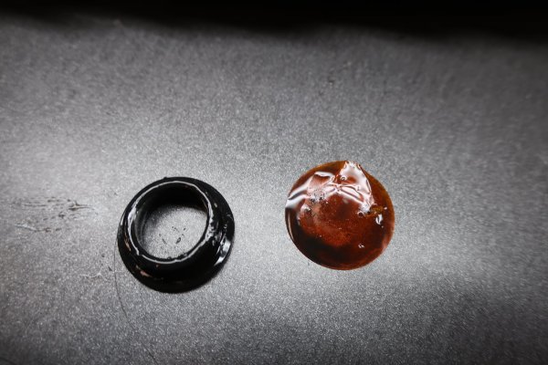
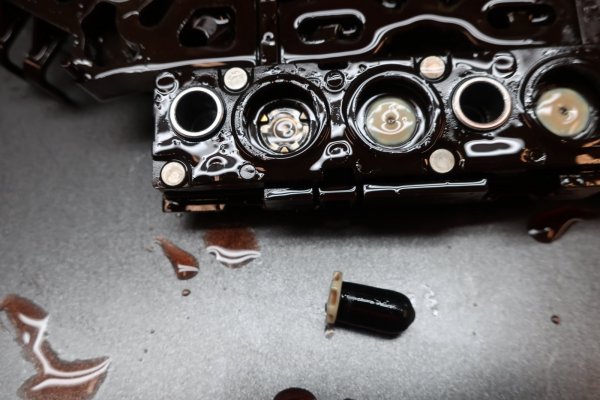
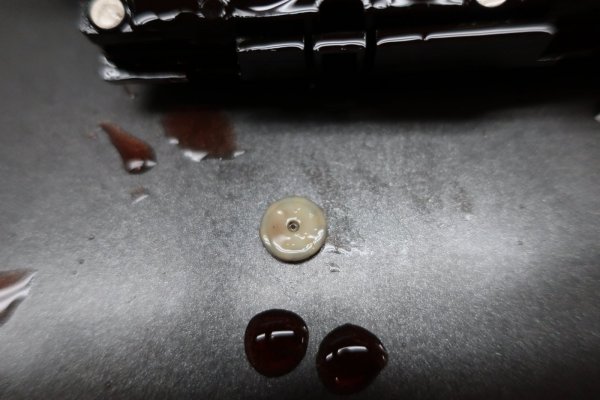
The seal and disc removed. NOTE: this disc got deformed as part of the removal process. It is well documented in the Sonnax pressure switch rebuild instructions.


Now, I do take umbrage at part of the Sonnax video for rebuilding the pressure switches: Under the disc, is the white plastic actuator for the pressure switch underneath. In the video, the technician effortlessly removes the actuator with a pick. Yeah. BS. I could not get any of the actuators to come out with a pick for love nor money.
So...I got creative. I used a little vacuum cap for suction. I squeezed the cap pressed into the actuator. The little bit of suction generated was enough to hold onto the actuator and pull it out.


2021-10-24 102.JPG
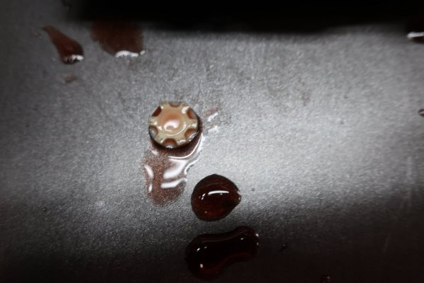
The white plastic actuator for the pressure switch. That did NOT come out effortlessly with a pick.


2021-10-24 103.JPG
My solution to the problem: suction with a vacuum cap. It was a bit finicky to get the cap on the actuator and squeeze it so the suction held, but it worked.


2021-10-24 104.JPG
Actuator removed.
 
Last edited:
OP
OP
skpyle

skpyle

Full Access Member
Joined
May 15, 2021
Posts
414
Reaction score
1,087
2021-10-24 105.JPG
Scalloped underside of the actuator.


2021-10-24 106.JPG
The actual pressure switches themselves, under the seal, disc, and actuator.


2021-10-24 108.JPG
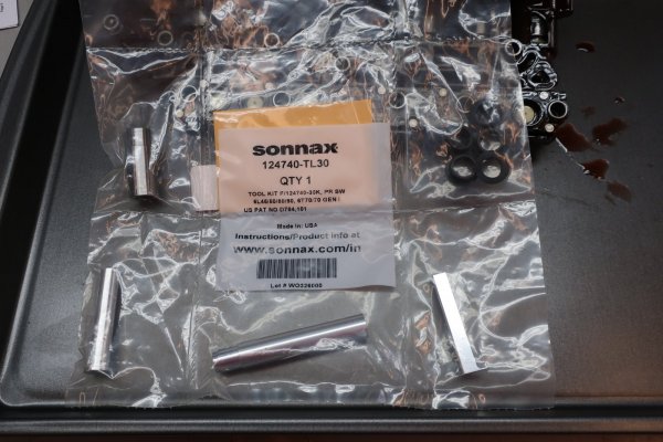
The Sonnax pressure switch rebuild kit and tools set I bought off ebay. You really want the tool kit. Cough up the $35 or so it costs. Listen, I don't care how much of a Billy Bad-A$$ you think you are, getting the seals installed without killing them without the special tool is going to be soul killing. Buy the tool kit.
This kit I bought off ebay had 5 seals and 5 discs. 4 needed plus 1 for screw ups. I ended up later buying an additional 5 deals and discs alone to have on hand for 75,000 miles from now, or so.


2021-10-24 109.JPG
New discs and seals installed in the pressure switches.


There is alot that happened to get to this photo. As per the instructions, I blew out the pressure switches with 30PSI air to clear any debris. Then, after watching the video around 30 times, and having it playing as I did the work, I started installing the discs and seals.

My observations: The instructions are quite detailed and good for installing the dics and seals. It calls out all the little details. However, the video really brought it together. Seeing the technician use the tools made it that much clearer for me.

However...it was still nerve wracking!!! Granted, I had one spare. But that just meant I only had one chance to screw up and not be doomed.
My main concern was the fact that the discs had to be deformed a bit to fully install them. Once you have bent them into the inverted taco and slid one side into the bore, the other side sticks up and has to be forced down. The tool does this well, but I still had visions of crinkling or damaging the disc.
I got all four of them. In spite of myself.

Next...the seals. The instructions are good and the tool makes sense once you figure it out. However, make sure you firmly hold the outer part of the tool against the TECHM, and then more firmly push down the plunger. Don't stop pushing down on the plunger until the outer part of the tool pops up off the TECHM. Watch the video, it will make sense. I almost screwed up the first seal because I stopped pushing when it felt like the seal was in. The seal was close enough to being fully installed that I was able to massage it in place. There were curse words.
 
Last edited:
OP
OP
skpyle

skpyle

Full Access Member
Joined
May 15, 2021
Posts
414
Reaction score
1,087
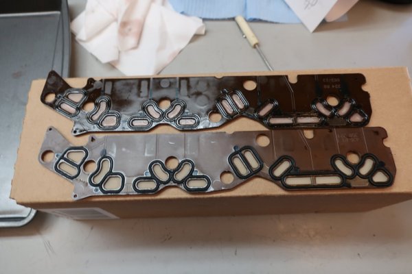
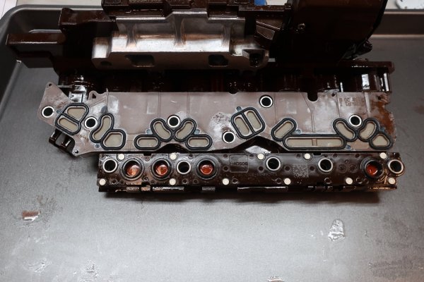
Next step after rebuilding of the pressure switches was replacement of the shift solenoid filter plate. I purchased a new GM 24236934 Plate Kit, Control Solenoid Valve Filter. Note: I researched this on gmpartsgiant.com. Beware, there are a couple of different versions of this filter plate. Make sure you get the one that applies to your particular 6L80.

Removing the old filter plate was a bit concerning. The Sonnax ZIP kit instructions recommend replacing this plate everytime the TECHM is removed from the valve body, because the seals take a set. The service manual warns to not break off any of the 4 locator tabs on the TECHM for the filter plate. Well...the TECHM is plastic, the tabs are plastic, the filter plate is plastic, and it is on there pretty tight.
I did not break any tabs, but was overly cautious in removing the filter plate. I used a combination of screwdrivers and picks to gently lever it up and off the tabs.
Reinstallation was gently pushing the new filter plate down onto the tabs.

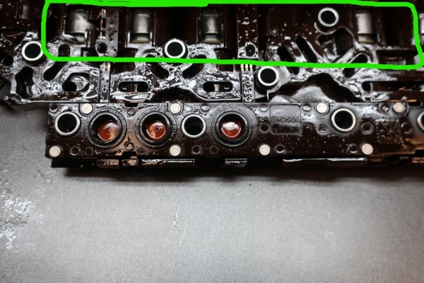
Now, I did screw something up... The ZIP kit instructions say to inspect the shift solenoids and blow them out with 30PSI air. I got part of that right. I inspected the solenoids in the TECHM, and noted the had a little grey film of sludge on them. However, I got wrapped up in the pressure switch rebuild and forgot to blow out the solenoids with air. Grrr...
(EDIT: transmission shifts and works properly after all this work, so the solenoids are functioning properly.)


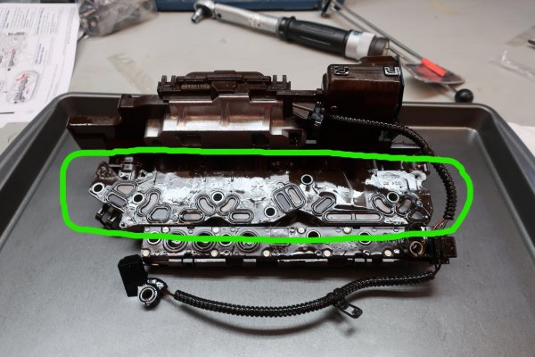
2021-10-24 095_LI.jpg
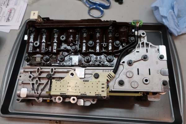
Shift solenoid filter plate, circled in green.


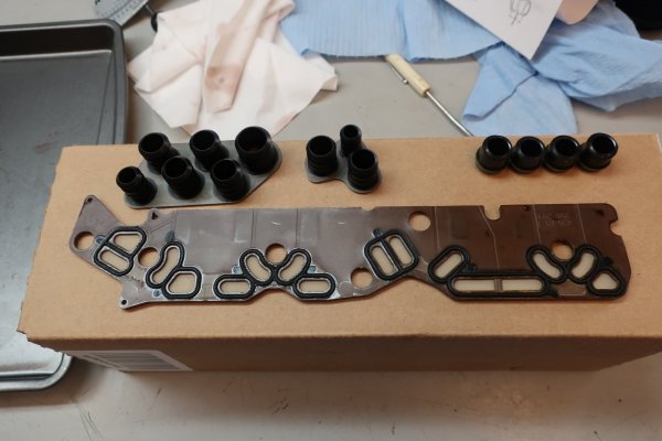
2021-10-24 110.JPG
New GM shift solenoid filter plate. This kit also included the three seal stack sets, a couple of large O-rings, and new OE checkballs. I left the O-rings and checkballs in the bag, because I didn't use them.


2021-10-24 109_LI.jpg
Shift solenoids, circled in green.


2021-10-24 111.JPG
Old filter plate at top, new filter plate at bottom. I compared them closely to make sure they were identical.


2021-10-24 113.JPG
New filter plate installed on the TECHM.
 
OP
OP
skpyle

skpyle

Full Access Member
Joined
May 15, 2021
Posts
414
Reaction score
1,087
Now that the TECHM was done, next step was to reassemble all the various parts back on the valve body. I followed the reassembly steps in the Sonnax ZIP kit instructions, paying attention to torque spec and sequence.


2021-10-24 116.JPG
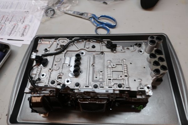
Valve body with the TECHM and position switch reinstalled.


2021-10-24 115.JPG
Valve body with input/output speed sensors and harness reinstalled, as well as all three seal stacks.


2021-10-24 114.JPG
Comparing old seal stacks that came out of the transmission with the new ones that came in the filter plate kit.
 
OP
OP
skpyle

skpyle

Full Access Member
Joined
May 15, 2021
Posts
414
Reaction score
1,087
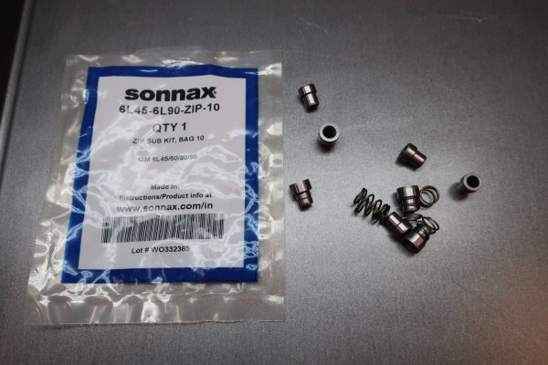
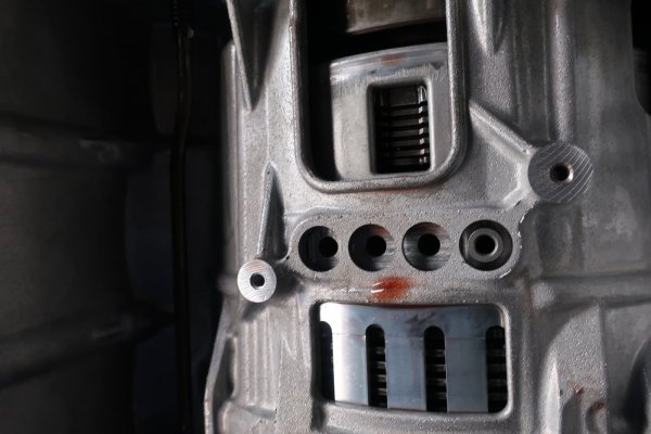
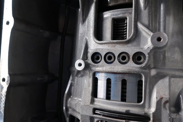
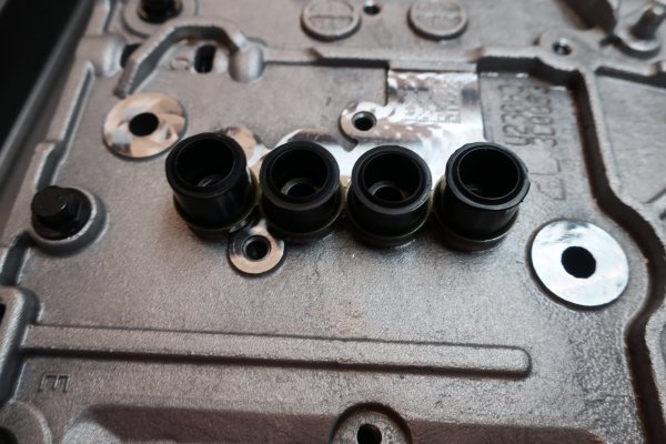
One more step before I could reinstall the completed valve body back into the transmission case. I had to install the other half of the Sonnax Center Seal Support kit. I installed the four steel bushings that were grooved into the transmission case. No brass block here, as the bushings sat in wells. I used an appropriately sized punch and reasonable hammer force. No problems.


2021-10-24 090.JPG
Sonnax Center Support Seal kit. Bushings with the grooves go into the transmission case.


2021-10-24 117.JPG
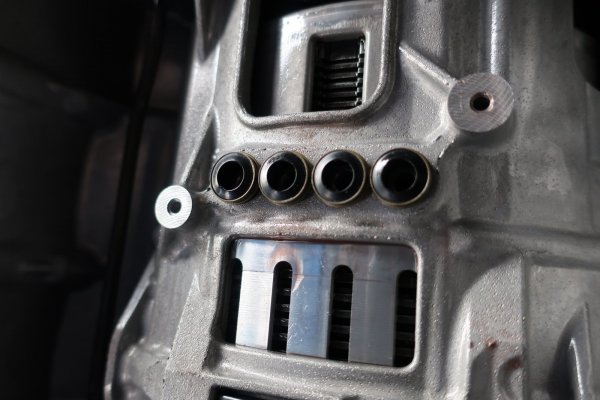
One bushing tapped in. You can see the holes at the bottom of the wells.


2021-10-24 118.JPG
All bushings tapped in. That is not an optical illusion. The center two bushings sit higher than the outer two bushings.


2021-10-24 094.JPG
It is difficult to see in this photo, but the outer two seals are taller than the inner seals. This matches how the center support bushings in the transmission case sit higher. As per the Sonnax instructions, the short 0.250" springs inside the outer two seals only. I held them in place with petroleum jelly. I then installed the seal stack in the transmission case, over the steel bushings. And hoped like h*ll the spring pressure didn't push the seals off before I got the valve body installed.


2021-10-24 119.JPG
Seal stack installed in the transmission case.
 
OP
OP
skpyle

skpyle

Full Access Member
Joined
May 15, 2021
Posts
414
Reaction score
1,087
Installing the valve body was a real treat...

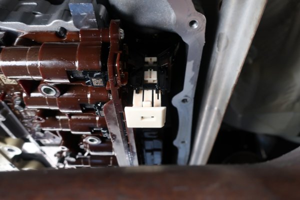
I was concerned with aligning the bushings for the center seal stack on the valve body with the seal stack installed in the transmission case. Because I had to install the back of the valve body first to engage the electrical connector, then tilt the front of the valve body up. Also, don't forget to make sure the black plastic plunger on the position indicator switch lines up correctly the manual shift shaft lever. I got it the first try, though it was a bit nerve wracking. There is no way to see the seal to see if it went in. I just went by feel. IE the valve body felt flat against the transmission casing with no rocking. I started all six EP10 Torx Plus bolts and tightened them hand tight.

And then remembered the white latch for the electrical connector.
And it wouldn't latch. I tried pushing a touch harder. Bad idea, things started flexing.
I tried manipulating the latch back and forth. Side to side. Nothing.
I loosened the valve body mounting bolts and gently pushed the valve body towards the electrical connector.
Nope.

2021-10-24 120.JPG
Electrical connector latch. Not latched.


So...I pulled the valve body back out. I did find that none of the center seals were deformed, so I did get it right on install.

Back on the work bench, I looked at the latch. I looked at the electrical connector on the TECHM. And found nothing wrong. I tried pushing the latch. It would not go.

I performed google-fu for valve body electrical connector. I watched videos. Only one had anything to do with the electrical connector, and it was for the plug outside the case. Which wasn't my problem. (Ominous foreboding music...)

Looking closer, there are two little metal 'fingers' at the bottom of the latch. I gently pushed the fingers towards the TECHM with a pick and pushed down on the latch.
CLICK. It latched.
This told me the electrical connector wasn't seated properly.

Hmmm...if the valve body can't move any closer to the connector (because of the center seal stack and the mounting bolts), then maybe the case electrical connector isn't right?
That thought scared the bejezzus out of me. I really don't like damaging things on my new toys. Especially ones I need to drive daily.

Back under the Escalade, I stuck my head up behind the transmission to look at the electrical connector on the outside of the case. I gently pulled on the cable to see if it was tight. And the whole thing came off and out of the transmission. And I deposited ***** matter into my undergarments.

After learning to breathe again, I remembered the useless youtube video I watched on the electrical connector that wasn't my problem. It discussed how the outer electrical connector was a twist lock type of connector. OK...

I reinstalled the valve body. I then gently pushed the electrical connector back into the transmission case and turned as I went. I turned and then fell into position. I gave it a little push and the off-white latch on the connector latched into the transmission case.
Back at the valve body, I pushed on the electrical connector white latch. It latched.
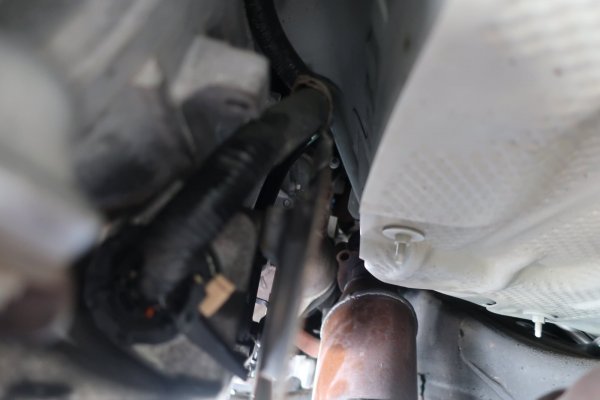

2021-10-24 124.JPG
Electrical connector at the back of the transmission case. Note the off-white latch and the black lever sticking out to the right...
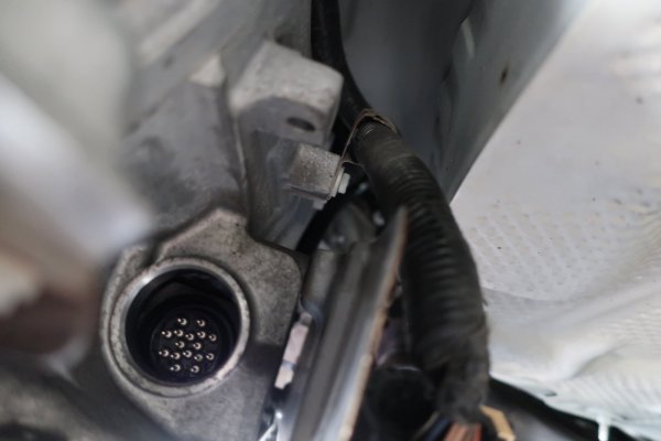

2021-10-24 122.JPG
View of the electrical connector on the TECHM through the port in the transmission case from the outside. If you zoom in, you can just see the spiral grooves in the connector locking sleeve inside the port.
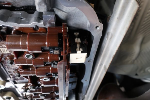

2021-10-24 123.JPG
Electrical connector latch. Latched.


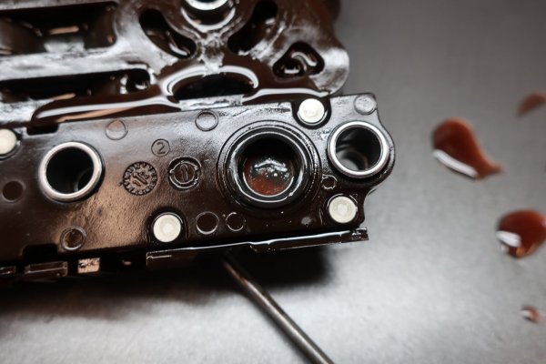
2021-10-24 126.JPG
Finally. The valve body was completely reinstalled.
 
Last edited:
OP
OP
skpyle

skpyle

Full Access Member
Joined
May 15, 2021
Posts
414
Reaction score
1,087
Next step, install the new transmission pan with the welded nut and drain plug.
I require a drain plug the automatic transmission pan of any vehicle I own. Whether it had one to begin with, or if I have to add one as I go.
My plan was to have my machinist weld a nut to the bottom of this pan while I was doing all of this transmission work. Yes, I know, I am dirt because I cannot weld. It is what it is.
For giggles, I looked up the price of a new transmission pan for the 6L80 in an Escalade.
GM 24222657, $15 on Rock Auto! $24 on Amazon!!! SOLD

I found a suitable drain plug, gasket, and nut. I drilled a hole in the pan in a location I felt suitable based upon google-fu. I have screwed this up in the past. This time I made sure just in case that the drain plug tip didn't protrude far into the transmission pan. I then delivered all of that to my machinist to be welded. We did the same thing to the pan on the Explorer's 4R70W.

A bit of philosophy. I have the nut welded to the outside of the pan so the most fluid will drain out. If the nut is on the inside, then you will still have the thickness of the nut level of ATF in the pan. Which can be a considerable amount. Ground clearance is not an issue with this pan, so I had plenty of room to put the nut and drain plug on the outside.

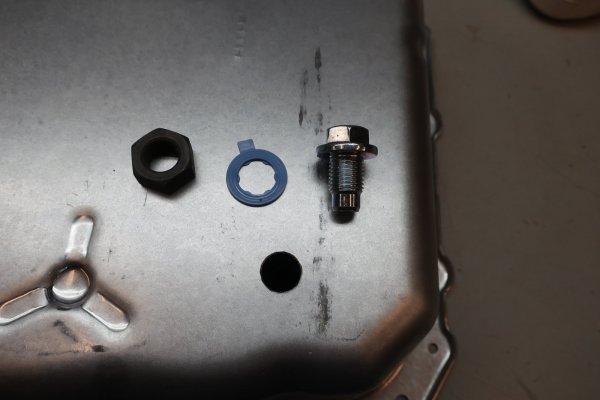
2021-10-14 007.JPG

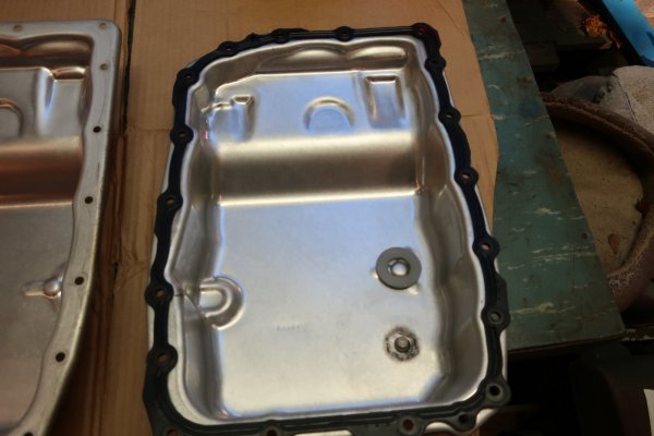
New pan, hole, nut, gasket, and drain plug.


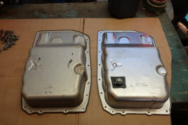
2021-10-24 127.JPG
Comparing old pan at left to new pan at the right.


2021-10-24 129.JPG
Cleaned magnet and gasket go on the new pan. The old pan goes back into the box for the new pan and will be stored away for future use.


2021-10-24 130.JPG
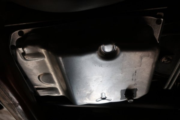
New transmission pan installed on the transmission.
 
OP
OP
skpyle

skpyle

Full Access Member
Joined
May 15, 2021
Posts
414
Reaction score
1,087
Next step is to reinstall the exhaust. I put some high temp nickel antiseize on the exhaust manifold down pipe studs so I can do this again in the future.

I installed new manifold to down pipe seals before pushing the down pipes back up into place at the manifolds.
For the driver's side, it was a conical 'donut' seal that lightly pressed into the exhaust manifold outlet. GM 1503747.
For the passenger's side, it was a crush ring type seal that sat in a receiver groove in the top of the flange on the down pipe. GM 15077362. I had to install that one by Braille.

With the seals in place, I pushed the down pipes back up to the manifolds and started the six nuts by hand. I ran all six nuts down as far as I could by hand.
This time, I did not need the 15mm flare crows foot. I was able to get the 15mm deep well socket on all the nuts, though I needed the universal joint for a couple. Torqued all the nuts and called it done.


2021-10-24 131.JPG
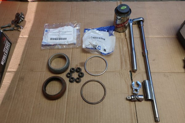
New exhaust down pipe seals at top, old seals at bottom, nuts, antiseize, and tools of war. Ended up not needing the flare crows foot.


2021-10-24 133.JPG
Driver's side down pipe securely fastened to the manifold again.


2021-10-24 132.JPG
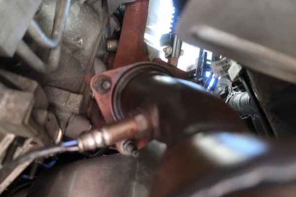
Passenger's side down pipe securely fastened to the manifold again.


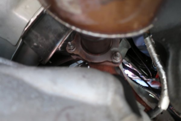
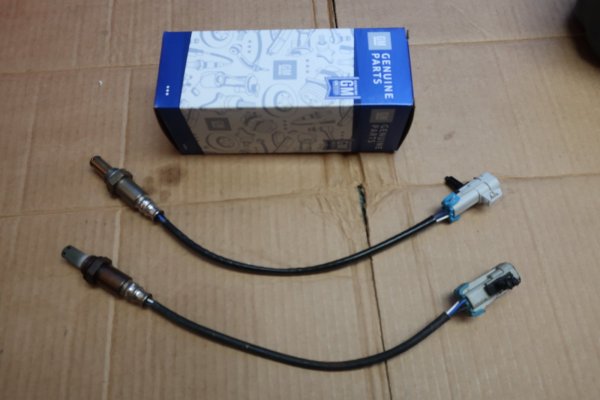
Last step for the exhaust was to install a new GM 213866 oxygen sensor in the passenger's side down pipe and connect the wiring plug.


2021-10-24 134.JPG
New heated oxygen sensor at top, still functioning 123,*** mile sensor at bottom.


Nope: forgot a step.
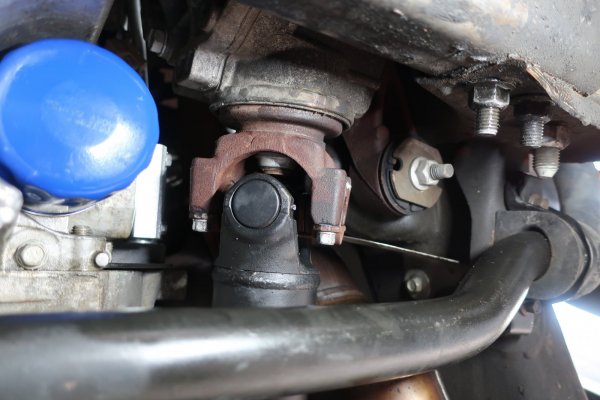
I reconnected the front drive shaft to the front axle. I had to turn the input yoke a touch to get the U-joint to line up, but I got it.


2021-10-24 137.JPG
Front drive shaft and U-joint back where they belong.
 

Forum statistics

Threads
132,361
Posts
1,866,711
Members
96,984
Latest member
Scpori
Top