You are using an out of date browser. It may not display this or other websites correctly.
You should upgrade or use an alternative browser.
You should upgrade or use an alternative browser.
RTV (silicone) posioned O2 sensor
- Thread starter firsthere
- Start date
Disclaimer: Links on this page pointing to Amazon, eBay and other sites may include affiliate code. If you click them and make a purchase, we may earn a small commission.
rockola1971
Full Access Member
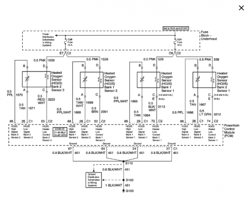
Heres a schematic for the 04 Tahoe. The symbol on the left of each sensor with the diagonal arrow pointing up and to the right are the actual 02 sensor of the whole sensor. The squiggly symbols to the right of each sensor element are the heaters. So just look at the wire colors and measure across the correct pair at each sensor. Each heating element circuit will have a pink wire on one side of the element. Just touch your meter the corresponding on the sensor, etc. (with wiring harness unplugged from sensor).I cannot tell which, the only pair with a measurement from the Ohm setting.
Fun Fact: The heater part of the sensor is fed power(12v+) by the 15a fuse directly to the sensor heater on one side. The PCM provides the ground on the other side. ON the 02 sensor part of it the PCM provides power and ground for each side of the sensor part.
Attachments
Last edited:
Thank you for the information.Heres a schematic for the 04 Tahoe. The symbol on the left of each sensor with the diagonal arrow pointing up and to the right are the actual 02 sensor of the whole sensor. The squiggly symbols to the right of each sensor element are the heaters. So just look at the wire colors and measure across the correct pair at each sensor. Each heating element circuit will have a pink wire on one side of the element. Just touch your meter the corresponding on the sensor, etc. (with wiring harness unplugged from sensor).
Fun Fact: The heater part of the sensor is fed power(12v+) by the 15a fuse directly to the sensor heater on one side. The PCM provides the ground on the side. ON the 02 sensor part of it the PCM provides power and ground for each side of the sensor part.
last time I measured some new ones I had around the same reading probably high 5 ohm's almost 6, the old one's measured slightly higher high 6's I have a tendency to burn thru cat's so I have tried to check the 02's first just to rule them out.Replaced both upstream sensors with unbranded ebay units. I figured if they were to contaminate again I'd rather be out just a few bucks. I already have AC delco sensors ready to go in if, when, needed.
Anyways, the sensor must have been the problem with the short as the new ones do not blow the fuse. It Is getting a latent P0171 (bank 1 lean) with No CEL. The idle is smooth and truck runs well though. Fuel trim on bank 1 is in the lower double digits so I will re-torque the intake and check all lines and sensors fittings. Could also be the new ebay O2 units I guess.
Just for reference, by Comparison of the new ebay sensors which were at 6.2 each and both original downstream sensors (still in use) are around 12 Ohms, Should that be a concern at the higher end service range (16 Ohms max) thus need to be replaced as well? Also, does the static O2 sensor resistance change fuel trim enough to worry about as long as its within the service range...
We took the tahoe out for a 25 mile trip, It seems to run fine although several new latent codes. P0171 was cleared and did not reappear after the drive.
New codes
P0327
Knock Sensor 1 Circuit Low Input (Bank 1 or Single Sensor)
P0420 & P0430
Catalyst System Efficiency Below Threshold (Bank 1&2)
P0442 & P0456
Evaporative Emission Control System Leak Detected (small leak)
P0446
Evaporative Emission Control System Vent Control Circuit
P0496 EVAP
Flow During Non-Purge Condition
P0567, P0568, P0674
Cruise Control Signal Malfunctions (worked on the tow/haul in column. Must have pulled a cruise wire)
Long Term Fuel trim is up near +15 on bank 1, +8 on bank 2.
My thoughts are the evap. tube along the intake has a crack/leak, it took some abuse during the R & R.
I replaced the MAF with a Delphi as it appeared damaged on one of the filament, LT Fuel trim came back in line but the same codes are still showing latent with new low and high idle code. Knock sensor is setting CEL. The replacement sensors are Dorman with new harness and Ohm 93 each. Truck appears to be low on power (same as the old motor) though not using excessive fuel (premium 92). No noticeable detonation, no misfire, idles well.
I'm not sure replacing the sensors would have any benefit at this point.
I'm not sure replacing the sensors would have any benefit at this point.
Similar threads
- Replies
- 3
- Views
- 520
- Replies
- 16
- Views
- 1K

