SOLVED: Another misfire chasing threads (2008 express van)

Disclaimer: Links on this page pointing to Amazon, eBay and other sites may include affiliate code. If you click them and make a purchase, we may earn a small commission.

Fless

Staff member
Super Moderator
Joined
Apr 2, 2017
Posts
12,140
Reaction score
24,745
Location
Elev 5,280
EDIT: I can't tell if "O2S11" is "side" 1, sensor 1; or "sensor" 1, side 1. Doesn't matter for that one, but how to tell which one is the bank 2 sensor 1 reading? Does your manual show the abbreviations?

Do you suspect cylinder 8 or 7 of an issue? It could be just about anything on the passenger side, so I don't think swapping just those two injectors would be conclusive, except by chance or luck.

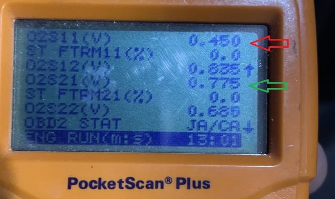
In the third pic, the S1 upstream sensor is at 0.450 V (red arrow), which indicates that it's not warmed up enough yet to work, or is essentially dead. You may want to swap the upstream sensors from side to side to see if the voltages follow or if there is something wrong with the sensor circuit. Or do some electrical tests to validate the circuit. I'm wondering if this issue could cause the trims on the driver's side to compensate, but I don't think they interact that way. S1-2 (passenger upstream?) sensor (maybe not the green arrow, but the one above it at 0.835v) does seem to be working somewhat, but graphs of those would be super helpful. The STFT on that side bothers me as it should be moving off of zero a little as long as the sensor is working properly. Do you ever see either STFT move off of zero?

An app like Torque Pro with a OBD dongle would allow graphing, as would some other apps.

298D652A-8A77-4362-BBF0-CE19072FA628.jpg
 
Last edited:

RED TAHOE LS

Full Access Member
Joined
Jan 2, 2017
Posts
774
Reaction score
409
Location
Rossville, Georgia USA
Details
2008 Chevy express 3500 cargo van 6.0
58k miles. 8k running hours. No service history

So after last weeks fun with the wife’s MB. (I think it’s resolved). my work van started having a rough idle. Code reader says P0307 misfire cylinder 7 confirmed. So I went and changed out the spark plugs (gapped to .040) and new wires. And did a half ass compression test because I didn’t realize how tight everything was. I tested the back 4 cylinders. All within 175-180psi. After this. I have p0302 code. Cleared then it came back. And it’s actually noticeably worse than it was before I changed the plugs. Now it rough idles then hard shifts into 2nd gear when accelerating from stop. Where oh where do I go from here

I originally had plans to move the coils around to see if the misfire follows. But I didn’t even get that far. And now it has gone to cylinder 2

Any advice is greatly appreciated

Let the engine cool off, get comfortable with a small flashlight, check the plug wires ONE @ A time by shinning the flashlight into each end of the plug wires as well as the distributor cap. The miss fire will leave a black sooty look in the connection area if bad.
 
OP
OP
Tonyv__

Tonyv__

Full Access Member
Joined
Apr 18, 2018
Posts
3,483
Reaction score
7,908
Location
Bucks county PA
EDIT: I can't tell if "O2S11" is "side" 1, sensor 1; or "sensor" 1, side 1. Doesn't matter for that one, but how to tell which one is the bank 2 sensor 1 reading? Does your manual show the abbreviations?

Do you suspect cylinder 8 or 7 of an issue? It could be just about anything on the passenger side, so I don't think swapping just those two injectors would be conclusive, except by chance or luck.

In the third pic, the S1 upstream sensor is at 0.450 V (red arrow), which indicates that it's not warmed up enough yet to work, or is essentially dead. You may want to swap the upstream sensors from side to side to see if the voltages follow or if there is something wrong with the sensor circuit. Or do some electrical tests to validate the circuit. I'm wondering if this issue could cause the trims on the driver's side to compensate, but I don't think they interact that way. S1-2 (passenger upstream?) sensor (maybe not the green arrow, but the one above it at 0.835v) does seem to be working somewhat, but graphs of those would be super helpful. The STFT on that side bothers me as it should be moving off of zero a little as long as the sensor is working properly. Do you ever see either STFT move off of zero?

An app like Torque Pro with a OBD dongle would allow graphing, as would some other apps.


View attachment 350148
So in manual. 02s11 is bank 1 sensor 1… 02s21 is bank 2 sensor 1..

According to my scanner misfire is on cylinder 7. (Driver side)

I only warmed the van for about 10 minutes before I started scanning. Which I thought would be sufficient… I’ll drive it a little today and try to monitor some live data on the road. I’ve never noticed if the St fuel trim fluctuated as this is my first time using the live data. I’m learning how to use it.

If the sensors don’t improve with a little driving. I’ll try to swap the 02 sensors or even order new ones. I’m sure they won’t come out without a fight..

I’ll also give that video a watch tonight about the injectors

also wonder if any HF scanners have graphing. As anything on Amazon won’t be here until late this week…
 
OP
OP
Tonyv__

Tonyv__

Full Access Member
Joined
Apr 18, 2018
Posts
3,483
Reaction score
7,908
Location
Bucks county PA
Let the engine cool off, get comfortable with a small flashlight, check the plug wires ONE @ A time by shinning the flashlight into each end of the plug wires as well as the distributor cap. The miss fire will leave a black sooty look in the connection area if bad.
I’ve moved the wires around a hand ful of times and replaced the spark plug in the problem cylinder just to be sure. I’m almost positive it’s not a ignition problem at this point. But thanks for the input
 

Fless

Staff member
Super Moderator
Joined
Apr 2, 2017
Posts
12,140
Reaction score
24,745
Location
Elev 5,280
So don't let the video sidetrack you, it's just an example of some tests that can be done if it leads to that. I think you mentioned that you tested all 8 injector circuits with a noid light, so the PCM/ECM should be switching the injectors.

When you fire it up cold, both banks' Sensor 1s should be sitting at 0.450v. Once the heaters and/or exhaust warm them up -- probably within a couple of minutes -- they should be switching rapidly over a range of 0.1 to 0.9v, especially as the RPMs change. Ignore the downstream sensors as those are only monitoring cat efficiency. If one of the upstream sensors continues to sit at the 0.450v level and doesn't change, suspect the sensor heater, the heater circuit, or the sensor itself. If the sensor heater is bad the sensor may start working if you drive the truck; idling probably won't heat up a sensor (with a bad heater) enough to wake it up.

Keep us up to speed with what you see.
 
OP
OP
Tonyv__

Tonyv__

Full Access Member
Joined
Apr 18, 2018
Posts
3,483
Reaction score
7,908
Location
Bucks county PA
So don't let the video sidetrack you, it's just an example of some tests that can be done if it leads to that. I think you mentioned that you tested all 8 injector circuits with a noid light, so the PCM/ECM should be switching the injectors.

When you fire it up cold, both banks' Sensor 1s should be sitting at 0.450v. Once the heaters and/or exhaust warm them up -- probably within a couple of minutes -- they should be switching rapidly over a range of 0.1 to 0.9v, especially as the RPMs change. Ignore the downstream sensors as those are only monitoring cat efficiency. If one of the upstream sensors continues to sit at the 0.450v level and doesn't change, suspect the sensor heater, the heater circuit, or the sensor itself. If the sensor heater is bad the sensor may start working if you drive the truck; idling probably won't heat up a sensor (with a bad heater) enough to wake it up.

Keep us up to speed with what you see.
Ok I bought a scanner this morning from HF on my way to work. I recorded some data on the road. I’m gonna see if I can upload it to my laptop later so it’s easier to see instead of me trying to record the small screen with my phone camera.

when I leave today I’ll check to make sure the sensors are at .450v when I start up then watch from there.

appreciate you following through and helping me out
 
OP
OP
Tonyv__

Tonyv__

Full Access Member
Joined
Apr 18, 2018
Posts
3,483
Reaction score
7,908
Location
Bucks county PA
@Fless

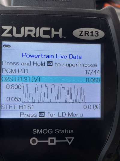
so with this new scanner I’m seeing reversed readings. I couldn’t get either one to rest at .450 my van must still be hot from this morning. But the 02b1s1 is bouncing up and down like you said. 02b2s1 is a little more unpredictable

So of course just my luck and no research. This scanner doesn’t work with mac. I was hoping to see the live data on a larger screen

edit. The windows software is only there to update the scanner. Not much more. So I’m only working with the little screen. I did notice my stftrm was fluctuating from 0.0 to negatives and above negative to low 2s then back to negatives. They did not stay at 0.0
 

Attachments

  • 657DFA21-26C4-4C9D-9913-B3241D9B4617.jpeg
    657DFA21-26C4-4C9D-9913-B3241D9B4617.jpeg
    318.8 KB · Views: 7
  • E833E915-BCE4-408E-BE02-CB7DD2E735F0.jpeg
    E833E915-BCE4-408E-BE02-CB7DD2E735F0.jpeg
    379.1 KB · Views: 7
Last edited:

Fless

Staff member
Super Moderator
Joined
Apr 2, 2017
Posts
12,140
Reaction score
24,745
Location
Elev 5,280
Well at least it looks like they're working. Weird that the scanner has fuel trims for the downstream sensors. For B2 S1, does the scanner show a STFT and does it move around a bit? (The first pic has STFT for B1 S2, which I think is bogus.)
 
Last edited:
OP
OP
Tonyv__

Tonyv__

Full Access Member
Joined
Apr 18, 2018
Posts
3,483
Reaction score
7,908
Location
Bucks county PA
Well at least it looks like they're working. Weird that the scanner has fuel trims for the downstream sensors. for B2 S1, does the scanner show a STFT and does it move around a bit? (The first pic has STFT for B1 S2, which I think is bogus.)
Yeah I edited the post. The stft does not stay at 0.0 like previously. It hovers into the negatives and up to about 3

patiently waiting for my scope to come in and I ordered an intake gasket for the hell of it. Trying anything at this point
 
OP
OP
Tonyv__

Tonyv__

Full Access Member
Joined
Apr 18, 2018
Posts
3,483
Reaction score
7,908
Location
Bucks county PA
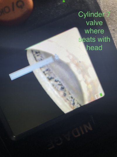
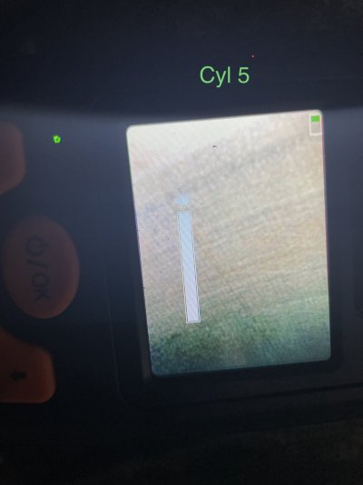
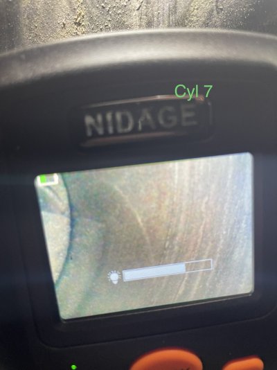
So I scoped the cylinder and I definitely see some scratches but I don’t know when it’s considered to be failed rings. I pictured cyl 5 for reference and I also see some light scratching. The pic quality is crap so bear with me. I didn’t realize how hard it would be to take pics of a small screen with my phone
 

Attachments

  • 54C0F195-6B60-4650-A7F0-9DA342ACFAD8.jpeg
    54C0F195-6B60-4650-A7F0-9DA342ACFAD8.jpeg
    200 KB · Views: 7
  • 433DF44A-143C-4C1A-B122-7335B742974F.jpeg
    433DF44A-143C-4C1A-B122-7335B742974F.jpeg
    231.7 KB · Views: 7
  • F2956440-E55A-47A7-9833-648852ADB3CD.jpeg
    F2956440-E55A-47A7-9833-648852ADB3CD.jpeg
    250 KB · Views: 8
  • 6E704D05-42D6-4B55-BA22-22E7B467CD96.jpeg
    6E704D05-42D6-4B55-BA22-22E7B467CD96.jpeg
    225.1 KB · Views: 8
  • 14C32FB2-F5F1-4992-95AA-81A8FF1B6DDF.jpeg
    14C32FB2-F5F1-4992-95AA-81A8FF1B6DDF.jpeg
    244.8 KB · Views: 8

Forum statistics

Threads
132,703
Posts
1,872,850
Members
97,517
Latest member
Reed198899
Top