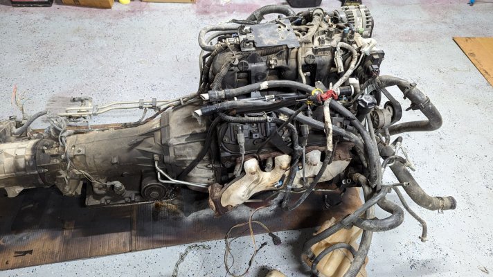
Testing the transmission on your own dyno ain't happening unless you have tons of money to invest in one and/or time fabbing one up from spare parts from the junkyard. And if you do, why not just go into business as a transmission shop at that point? Invest those funds into some of the specialty tooling you'll need if you don't already have (sealing ring sizers, foot press, shop press, bushing drivers, etc). That said, 4L60Es are fairly straightforward from a builder's perspective however there are some areas that you really need to pay attention to:
> Always provide a new torque converter w/all rebuilds
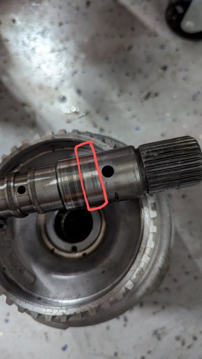
> Forward drum - pressure test all of them before disassembly as many of them leak where the shaft is pressed into the drum, especially at the 2-3 feed and you'll have 3-4 pack failure shortly after it goes back in
- Set the 3-4 clutch pack clearance to .035-050 on reassembly (replace the steels, apply and backing plates) - also have different thicknesses of steels and use Kolene or lindered steels for performance
- Leave the load release springs out of the 3-4 pack unless your clearance is less than .035 then install one spring per retainer - you don't need both
- Install Transgo's high-rate return spring kit for high performance builds
- Install a 4L65E spec 3-4 pack or aftermarket Max Pack from BW, Alto or Raybestos (except the Z-pack, I'm not a fan of that product) for anything performance
> There are no molded frictions (thinking you meant to say molded pistons) - retro those and the corresponding late model return spring into any 7004R4 and pre-97 4L60E you build; account for it in your pricing model
> Pump - an overwhelming majority of them need resurfacing so you'll need to find a good machinist with a lathe and mill who specializes in transmission-related machine work
> check the stator bore for sealing ring groove wear and/or cracks - I see this more on later models (2006-2009) for some reason more so than other years/vintages
> Your machinist will also tell you if the stator was ever reinstalled and done so incorrectly as there will be noticable run out when it's spinning in the lathe
> Forward sprag and sprag gear assembly - replace the forward sprag one-way clutch on all overhauls (Borg Warner 29-element) - recondition the outer race with some 400g sand paper or emery cloth to reintroduce x-hatching for the sprag to 'bite' into
> Replace ALL BUSHINGS - especially the pump bushings; use the Sonnax rear stator bushing and wide rear sun gear bushing for anything remotely performance (or on all rebuilds to mitigate risk in those spots)
> Sun shell - replace w/a hardened-heat treated version as the factory ones should never be reused (Install the Sonnax Smart shell for anything high HP/performance)
> Reverse Input Drum - most need turning or replacement as the band surface is usually warped
- Install a Sonnax pump body bushing in the rear position on all performance builds
> All electrical/electronic parts - always replace, never re-use!
> Set front end play somewhere between .015-.025 - have different sizes of selective spacer on hand for these plus Sonnax front end play shim kits
> Air check the case once fully assembled using a test plate - these have saved me numerous times over the years by catching instances where one or more of the turbine shaft sealing rings got messed up when installing the pump
Install a Transgo SK4L60E on all rebuilds or do the following yourself:
> Valve bodies - always vacuum test the AFL and TCC regulator-isolator valve trains; block the 3-2 downshift valve on anything moderate to high performance
- Convert the PWM to on-off by blocking the isolator valve inboard (Fitzall makes special valves for this-$25.00) - do this on all models except those going in behind engines w/VVT
- Block the 3-2 downshift valve inboard with either an extra buffer spring from the boost/PR valve train in the pump or something else of appropriate dimensions (high performance)
- Take the 3-2 downshift spring you pulled from that valve and install it inside of the AFL valve's main spring to make more AFL pressure available to solenoids (high performance)
> Block the 3-4 accumulator off in the case if you build anything that has greater than a 2200 stall; otherwise install the spring then the piston (find a stiffer spring if you can)
> Set servo travel between .075-.125; ensure band travel does not exceed .125 along the drum
> Drill the spacer plates as follows:
- 1-2 feed (.076-.093, depending on stall, type of second gear servo installed, application, etc)
- 2-3 feed - drill to .093 - .100 for stock to mild/moderate performance, up to .125 for wild and crazy with stalls > 4000
- 3-4 feed - drill to .093 - .100 for stock to mild/moderate performance
- band release - drill .093-.100 to match what you've drilled for the 2-3 feed
- low reverse - drill to .086 and remove low reverse check ball if a heavy duty application or high performance where burnouts will start in manual low
- Do NOT drill the TCC regulator or AFL balance feeds - enlarging those orifices will lower pressure in those hydraulic circuits unless you purchase Transgo's kit then drill them per Transgo's instructions
ETA - provide customers with a sheet that tells them how to fill their transmission, what fluid to use (DEX/MERC or 6) and how much fluid the system takes...Also give them another sheet the reminds them to flush their cooler lines and transmission cooler(s) before installation - I've had a few come back due to coolers being restricted with clutch material/debris and they tried to claim warranty and got denied (they paid again to have me fix the problems)
Here's the main thing you really need to know before getting into building transmissions for the public - you must truly understand how these things work. You don't want to find yourself in a position where someone's on the phone with you telling you that the transmission you just built for them isn't functioning correctly and you have absolutely no idea why or what to do about it.
I have a bunch of 4L60E vids on YT that cover everything from complete rebuild procedures to high performance and everything in between - links in my signature. Check them out if you need additional guidance and let me know if you have any ?s.
Good luck with the endeavor.


