#1 and #5 injectors not firing

Disclaimer: Links on this page pointing to Amazon, eBay and other sites may include affiliate code. If you click them and make a purchase, we may earn a small commission.

JDOG

TYF Newbie
Joined
Dec 9, 2017
Posts
5
Reaction score
3
Hi all,
I have a 2013 Yukon Denali with the 6.2 engine. It has 115k miles on it. Lost a couple AFM lifters about two years ago, so parked it and just finished installing a BTR cam kit with AFM and VVT delete and a Black Bear tune. It starts and runs, but won’t fire the #1 or #5 injectors. I’ve checked everything I can think of…….compression 175-180 on all cylinders, swapped coils around, swapped injectors around, checked wiring harness, getting 12V to all injectors with ignition on and with engine running, checked continuity in all wiring to injectors, tried two different ECMs with and without tunes(no change), and checked all injectors with Noid light. Computer doesn’t seem to be telling #1 and #5 injectors to fire. #1 and #5 plugs are dry when I check them. Any help any of you can give would be greatly appreciated. No DTCs except “lean bank 1”. Thanks a bunch!
 

Geotrash

Dave
Supporting Member
Joined
Feb 16, 2018
Posts
6,423
Reaction score
15,916
Location
Richmond, VA
Hi all,
I have a 2013 Yukon Denali with the 6.2 engine. It has 115k miles on it. Lost a couple AFM lifters about two years ago, so parked it and just finished installing a BTR cam kit with AFM and VVT delete and a Black Bear tune. It starts and runs, but won’t fire the #1 or #5 injectors. I’ve checked everything I can think of…….compression 175-180 on all cylinders, swapped coils around, swapped injectors around, checked wiring harness, getting 12V to all injectors with ignition on and with engine running, checked continuity in all wiring to injectors, tried two different ECMs with and without tunes(no change), and checked all injectors with Noid light. Computer doesn’t seem to be telling #1 and #5 injectors to fire. #1 and #5 plugs are dry when I check them. Any help any of you can give would be greatly appreciated. No DTCs except “lean bank 1”. Thanks a bunch!
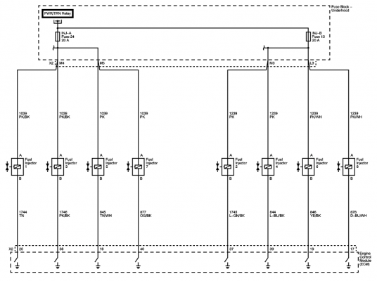
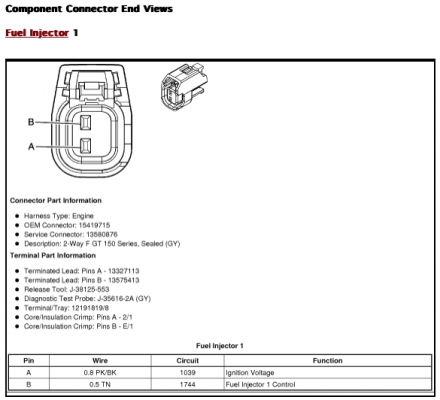
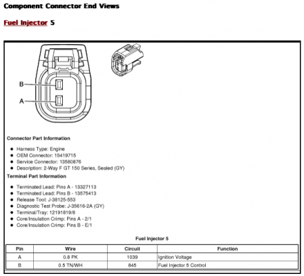
Thanks for sharing the details of all you've done up front. Helps a lot. With all of that, my money is on a bad ground since both cylinders share a common ground. Good that you have 12V to each, but a bad or weak ground could be the root cause.

Edit: After I said this I looked at the wiring diagram and the diagnostic procedure. This, for a 2012 Yukon XL Denali. Note that more advanced tests require a pricey CH-48976 active fuel injector tester.

1715632299518.png

1715632730298.png
1715632761187.png

Circuit/System Description

The engine control module (ECM) enables the appropriate fuel injector pulse for each cylinder. The ignition voltage is supplied directly to the fuel injectors. The ECM controls each fuel injector by grounding the control circuit via a solid state device called a driver. A fuel injector coil winding resistance that is too high or too low will affect the engine driveability. A fuel injector control circuit DTC may not set, but a misfire may be apparent. The fuel injector coil windings are affected by temperature. The resistance of the fuel injector coil windings will increase as the temperature of the fuel injector increases.

The CH-47976 , is used to test the fuel pump, fuel system leak down, and the fuel injectors. Following the User Guide, CH 47976-11, and the on screen prompts or selections, will indicate the steps required to perform each of the available tests. The tester will perform all of the tests automatically and display results of the test. The results can also be down loaded for storage and printing.

Diagnostic Aids

  • Downloading the AFIT test results to the shop TIS terminal will clearly show which injector is at fault by the bar graph turning red.
  • On some vehicles cleaning the injectors may be performed if the graph shows erratic or values close to the specified values.
  • A second test can be performed to verify repair. Compare the first balance test to the second.
Special Tools

CH-47976 Active Fuel Injector Tester

Component Testing

Fuel Injector Coil Test


Verify the resistance of each fuel injector:

  1. Ignition ON, verify the scan tool ECT temperature is between 10-32°C (50-90°F).
¤If not within the specified range, measure and record the resistance of each fuel injector with a DMM. Subtract the lowest resistance value from the highest resistance value. The difference between the lowest value and the highest value should be equal to or less than 3 ohm. If the difference is greater than 3 ohm, add all of the fuel injector resistance values to obtain a total resistance value. Divide the total resistance value by the number of injectors to obtain an average resistance value. Subtract the lowest individual fuel injector resistance value from the average resistance value. Subtract the average resistance value from the highest individual injector resistance value. Replace the fuel injector that displays the greatest difference above or below the average.
  1. Test for 11-14 ohm between each fuel injector.
¤If not within the specified range, replace the fuel injector.
  1. If all the injectors test OK, refer to the Active Fuel Injector Tester (AFIT) Procedure.
Active Fuel Injector Tester (AFIT) Procedure

Note:


  • DO NOT perform this test if the engine coolant temperature (ECT) is above 94°C (201°F). Irregular fuel pressure readings may result due to hot soak fuel boiling.
  • Verify that adequate fuel is in the fuel tank before proceeding with this diagnostic.
  1. Verify the battery is fully charged and all accessories are OFF.
  2. Ignition OFF.
  3. Install the CH-47976 . Refer to the AFIT User Guide.
  4. Turn ON the AFIT and select the vehicle.
  5. Follow the setup screen on the AFIT.
  6. Ignition ON, perform the Injector Test. The test should run and pass all injectors.
¤If the AFIT aborts testing due to fuel pressure or fuel leak down, refer to Fuel System Diagnosis (FPCM) See: Computers and Control Systems\Testing and Inspection\Component Tests and General Diagnostics\Fuel System DiagnosisFuel System Diagnosis (Without FPCM) See: Fuel Pump\Testing and Inspection\Fuel System Diagnosis (Without FPCM).
¤If any injector exceeds the recommended tolerance, replace the injector(s), E-85 only. All other engines, refer to Fuel Injector Cleaning See: Service and Repair\Procedures.
 
Last edited:

strutaeng

Full Access Member
Joined
Aug 10, 2023
Posts
1,176
Reaction score
2,442
Location
Dallas, Texas
You can try back probing the faulty injectors directly pulsing signal from the ECU (and 12V+ and grounds) from the battery directly, as appropriate (according to the wiring diagrams.)

Probably something the wiring or ground would also be my guess...
 
OP
OP
J

JDOG

TYF Newbie
Joined
Dec 9, 2017
Posts
5
Reaction score
3
Thanks for sharing the details of all you've done up front. Helps a lot. With all of that, my money is on a bad ground since both cylinders share a common ground. Good that you have 12V to each, but a bad or weak ground could be the root cause.
Thanks for the reply. I was already suspicious of a ground somewhere. How should I go about identifying and testing? Am I looking for a chassis ground or an ECM ground? Guess I could hook my 12V test light to positive battery terminal and check the grounds in the injector harness? How is the ECM grounded?
 
OP
OP
J

JDOG

TYF Newbie
Joined
Dec 9, 2017
Posts
5
Reaction score
3
Also, where can I find a good engine harness wiring diagram? I’ve found a couple but they are blurry and hard to read?
 

Geotrash

Dave
Supporting Member
Joined
Feb 16, 2018
Posts
6,423
Reaction score
15,916
Location
Richmond, VA
Also, where can I find a good engine harness wiring diagram? I’ve found a couple but they are blurry and hard to read?
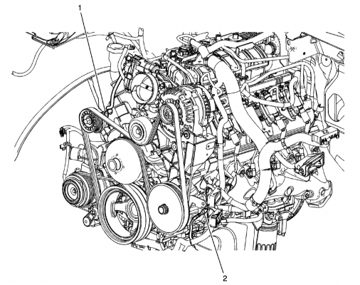
Best I've found is to subscribe to alldatadiy. Here are the ground points for the engine harness. I believe the ECU will ground the injectors through either #1 or #2, depending on the side of the engine. Note that I have also updated my post above with more details.

1715633305251.png
 

Geotrash

Dave
Supporting Member
Joined
Feb 16, 2018
Posts
6,423
Reaction score
15,916
Location
Richmond, VA
Sweet! Thank you!
Something to keep in mind: It's worth tracing the wires for the non-firing injectors back to the ECU - in particular the pulse signal wire. Each injector has two wires - one for the coil voltage and the other for the pulse signal from the ECU. The wiring diagrams above show what these are. You may find a damaged pin either at the injectors or the next connector upstream, or back at the ECU. My bet would be at the injectors or the next upstream connector, unless you removed the big bulk connectors at the ECU to complete the DoD delete work for some reason.
 

j91z28d1

Full Access Member
Joined
Feb 28, 2022
Posts
3,076
Reaction score
3,800
Something to keep in mind: It's worth tracing the wires for the non-firing injectors back to the ECU - in particular the pulse signal wire. Each injector has two wires - one for the coil voltage and the other for the pulse signal from the ECU. The wiring diagrams above show what these are. You may find a damaged pin either at the injectors or the next connector upstream, or back at the ECU. My bet would be at the injectors or the next upstream connector, unless you removed the big bulk connectors at the ECU to complete the DoD delete work for some reason.


this feels like the thing to do, especially since you've tried different ecm's.

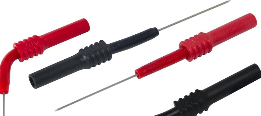
back probe the switched ground from the ecm to injector at the ecm plug itself. something like this to not damage the wires, pins or seals.

Img_2024_05_14_06_46_03.jpeg

I think you'll find you have it there but not at the injectors, meaning harness issues. if you don't have a switched ground at the ecm injector pin with multiple different test ecm's, that's whole difference level of broken that's byond me lol
 

Forum statistics

Threads
132,298
Posts
1,865,576
Members
96,884
Latest member
nscherr1
Top