2011 Tahoe no crank no start need help

Disclaimer: Links on this page pointing to Amazon, eBay and other sites may include affiliate code. If you click them and make a purchase, we may earn a small commission.

j91z28d1

Full Access Member
Joined
Feb 28, 2022
Posts
2,757
Reaction score
3,290
so I don't know the details on your truck but I looked up 2011 tahoe with a 5.3.

start wiring looks simple.. 5 volts out from bcm on X1 plug, pin 4 white wire. that runs to ign switch, in start it sends that back on a pink wire to pin 2 of the bcm called crank run.


I'd start by checking for voltage at the bcm out and then back in with the key held to start. if you have that then at least you have the basics and ruled out the ign switch failing.


looks like bcm sends the crank request over data lines to the ecm, ecm puts 12v on pin 52 yellow/black that runs on the crank relay. if you have crank request showing up on your scanner, check for power on that pin while doing it, it at the relay, probably easier.

check with your scanner that it shows the transmission in park or neutral. it needs that signal on the orange/black wire pin 1 of the ecm. it won't start without that either. on that note, is the gear indicator on the dash lighting up orange and following the gears? if so, try cranking in neutral too.
 

Attachments

  • PXL_20240810_122819376.jpg
    PXL_20240810_122819376.jpg
    547.6 KB · Views: 4
  • PXL_20240810_122829011.MP.jpg
    PXL_20240810_122829011.MP.jpg
    523.1 KB · Views: 5
  • PXL_20240810_123048762.MP.jpg
    PXL_20240810_123048762.MP.jpg
    596.1 KB · Views: 5
  • PXL_20240810_123114835.jpg
    PXL_20240810_123114835.jpg
    496.1 KB · Views: 5

j91z28d1

Full Access Member
Joined
Feb 28, 2022
Posts
2,757
Reaction score
3,290
Yes it does, says crank signal yes as I turn the key. Crazy everything seems like it should turn over but doesn't. Can bus lines are all good 60 ohms battery disconnected. It's gotta be computer problems.


if that's the case, I have a bad feeling the shop didn't reprogram the replacement parts correctly. but that's a bit of a hassle and money to test.

I see there's a start fuse. 40amp #62. any chance it's blown?
 
OP
OP
R

Rockman101

Member
Joined
Nov 6, 2023
Posts
30
Reaction score
29
if that's the case, I have a bad feeling the shop didn't reprogram the replacement parts correctly. but that's a bit of a hassle and money to test.

I see there's a start fuse. 40amp #62. any chance it's blown?
It's good. Starter works jumping relay. I think your right. Something isnt fully programmed. I don't have the equipment to program. Maybe I can just bring the ECM and bcm to them to test. I'm not sure.
 

j91z28d1

Full Access Member
Joined
Feb 28, 2022
Posts
2,757
Reaction score
3,290
so the ecm isn't sending 12v to the relay when the scanner is saying start requested. huh, you might double check that at the ecm pin itself just in hopes it's a wiring issue from ecm to fuse box.

unless you know of a shop or some one that specializes in programming stuff, I don't even know if that exists. the dealer can be a hassle about programming stuff. call ahead first and make sure you guy the name of the service writer if he says yes. I have read they have told people no and wouldn't touch it because it wasn't bought and installed from that dealer. even thou some of the parts are not available at gm anymore and must be bought used off ebay or junk yards. I don't understanding the reasoning for it at all.. an hours labor is the same no matter what.


you can buy a dongle that can be used as a pass thru to program modules in your truck yourself. it's a bit of a hassle cause gm's web site is about as reliable as their valve train these days. but 140$ dongle, 50$ at acdelco site to license the vin for 2 years to access their software and flash it. you will also need a good laptop or computer, the acdelco site is very picky. my tuning laptop wasn't up to their min specs, so I had to burrow a work laptop. it was still on the low end of their specs and while it worked, it failed a few times. hard to say if it gm's software failure, youtube is full of angry mechanics making videos about it, or my slow laptop haha.


either way, maybe you can talk to the shop that replaced your parts, or if by chance you sitll have the old ones. plug them back in and start over.

I know shops never want to give you your own stuff back them for some reason.
 

j91z28d1

Full Access Member
Joined
Feb 28, 2022
Posts
2,757
Reaction score
3,290
so there's what my software says.. it's all pretty basic but just incase there's something in there to help that might have gotten missed. it does seem like that transmission sector is very important.


Circuit/System Description
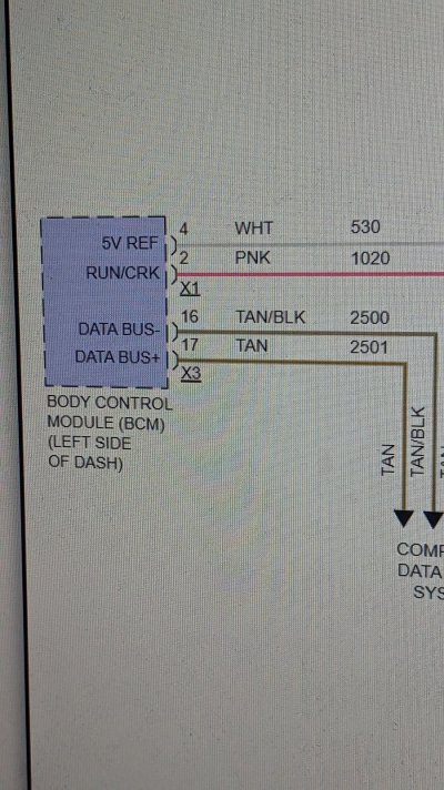
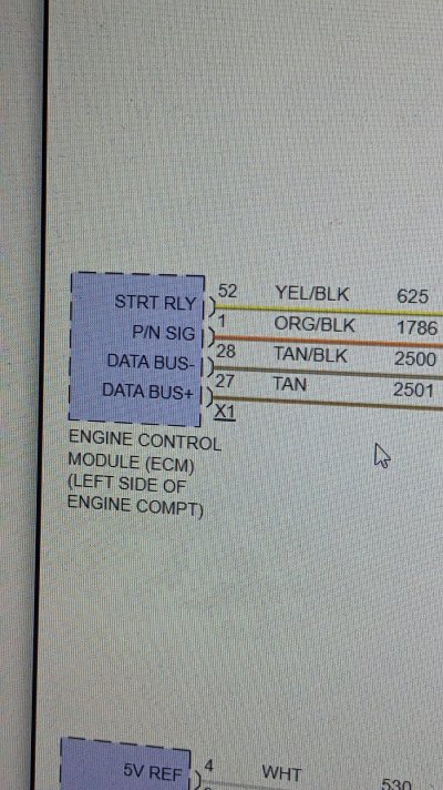
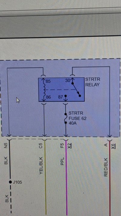
The engine control module (ECM) controls engine cranking based on a power mode input and the status of the park/neutral position (PNP) switch. With the transmission in Park/Neutral, voltage at the ECM PNP switch signal circuit is low. This indicates to the ECM that conditions are acceptable for cranking. When a power mode crank request is seen, the ECM applies voltage to the STRTR relay coil control circuit. This energizes the coil side of the relay, which pulls the switch side of the relay closed, applying voltage to the starter terminal S X2 and engaging the starter solenoid.

Diagnostic Aids
A misadjusted PNP switch (M30, M70) or shift control/range selector lever cable may result in a starter solenoid does not click condition.


Circuit/System Verification
Ignition ON, observe the scan tool ECM PNP Switch parameter while shifting the transmission through each range. The reading should change between Park/Neutral and In Gear.
If not the specified value, refer to PNP Switch Malfunction below.
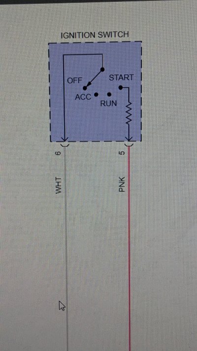
Command the Starter Relay ON with the scan tool, or turn the ignition switch to the START position. The starter solenoid should click and the engine should crank.
If the solenoid does not click, refer to STRTR Relay Malfunction below.
If the solenoid clicks but the engine does not crank, refer to Starter Solenoid Clicks, Engine Does Not Crank.
Circuit/System Testing
PNP Switch Malfunction (MYC 6L80E, MYD 6L90E)
Inspect the range selector lever cable for proper adjustment. Refer to Range Selector Lever Cable Adjustment .
Ignition OFF. Disconnect the 16-way harness connector from the transmission.
Ignition ON. Measure voltage on the park/neutral signal circuit terminal 3 with a DMM. Verify that there is greater than 10 V on the park/neutral signal circuit.
If there is less than 10 V on the park/neutral signal circuit, test the circuit for an open or a short to ground. If OK, replace the ECM.
Ignition OFF, reconnect the 16-way harness connector to the transmission.
Remove the automatic transmission fluid pan. Refer to Automatic Transmission Fluid, Fluid Pan and/or Filter Replacement .
Disconnect the manual shift shaft position switch connector at the control solenoid valve assembly. Refer to Manual Shift Shaft Position Switch Replacement .
Ignition ON, verify that the scan tool PNP Switch parameter displays In Gear.
If not the specified value, replace the ECM.
Connect a 3 A fused jumper wire between the park/neutral signal terminal F at the control solenoid valve assembly and ground. The scan tool PNP Switch parameter should display Park/Neutral when the terminal is connected to ground.
If not the specified value, replace the ECM.
If all components test normal, test or replace the manual shift shaft position switch.


STRTR Relay Malfunction
Ignition OFF, disconnect the STRTR relay.
Ignition ON, transmission in Park/Neutral. Verify that a test lamp illuminates between the relay coil ground circuit terminal and B+.
If the test lamp does not illuminate, test the ground circuit for an open/high resistance.
Probe the STRTR Relay switch B+ circuit terminal with a test lamp that is connected to ground. Verify that the test lamp illuminates.
If the test lamp does not illuminate, test the B+ circuit for a short to ground or an open/high resistance. If the circuit tests normal and the STRTR fuse is open, test the relay controlled output circuit for a short to ground.
Connect a test lamp between the relay coil ground circuit terminal and the relay coil control circuit terminal.
Ignition ON, transmission in Park/Neutral. Command the Starter Relay ON and OFF with a scan tool, or turn the ignition switch between the START and RUN positions. The test lamp should turn ON and OFF when changing between the commanded states.
NOTE: The engine may begin to crank.
If the test lamp is always ON, test the relay coil control circuit for a short to voltage. If the circuit tests normal, replace the ECM.
If the test lamp is always OFF, test the relay coil control circuit for a short to ground or and open/high resistance. If the circuit tests normal, replace the ECM.
Connect the START relay.
Install a test lamp between the starter terminal S X2 and ground.
Ignition ON, transmission in Park/Neutral, command the Starter Relay ON with a scan tool, or turn the ignition switch to the START position. The test lamp should illuminate.
NOTE: The engine may begin to crank.
If the test lamp does not illuminate, test the relay controlled output circuit for an open/high resistance. If the circuit tests normal, test or replace the STRTR relay.
If all circuits test normal, test or replace the starter.


Component Testing
Relay Test
Ignition OFF, disconnect the STRTR relay.
Test for 60-180 Ω between terminals 85 and 86.
If not within the specified range, replace the relay.
Test for infinite resistance between the following terminals:
30 and 86
30 and 87
30 and 85
85 and 87
If not the specified value, replace the relay.
Install a 20 A fused jumper wire between relay terminal 85 and 12 V. Install a jumper wire between relay terminal 86 and ground. Test for less than 2 Ω between terminals 30 and 87.
If greater than specified range, replace the relay.
Repair Instructions
Perform the Diagnostic Repair Verification after completing the diagnostic procedure.

Control Valve Body Assembly Removal for shift shaft position switch replacement (MYC 6L80E, MYD 6L90E)
Control Valve Body Assembly Disassemble for shift shaft position switch replacement (MYC 6L80E, MYD 6L90E)
Control Module References for ECM replacement, setup and programming.
 
OP
OP
R

Rockman101

Member
Joined
Nov 6, 2023
Posts
30
Reaction score
29
so there's what my software says.. it's all pretty basic but just incase there's something in there to help that might have gotten missed. it does seem like that transmission sector is very important.
Excellent thank you very much for your help. I think I need a shop. Checking voltage today I discovered I have no power to the yellow power relay wire. The head scratcher is no fuse is blown. I tested right at the bottom of the fuse block nothing zero volts
 

j91z28d1

Full Access Member
Joined
Feb 28, 2022
Posts
2,757
Reaction score
3,290
the yellow wire from the ecm to starter relay? that does need 12v while start in enabled, it's what turns the relay on.

I forget, can your scanner command the starter to crank? I know on the tech 2 there's a option engage the starter. that could narrow stuff down a bit too, since it tells the ecm directly to do it, doesn't involve the ign switch or the bcm.


I hope you find a good shop. first thing I'd do is ask the the counter guy if he's got a tech that's good with gm wirings. you've got a no start that has had a lot of parts thrown at it. Hopefully if he's at all decent he will tell you yes or no.
 
OP
OP
R

Rockman101

Member
Joined
Nov 6, 2023
Posts
30
Reaction score
29
Yellow wire from fuse box to ECM. My scanner can crank the engine. It cranks but doesn't start. Fuel pump primed, but no spark or injectors. Or if just rig a push button start and be done with it haha. Well I've learned a lot on this adventure canbus system. The more you know
 

j91z28d1

Full Access Member
Joined
Feb 28, 2022
Posts
2,757
Reaction score
3,290
aww so if it cranks with the scanner at least the ecm is good.

that yellow wire goes the other way around. it's not powered from the fuse box, the ecm is sending power to the fuse box, well the relay terminal that's in the fuse box. so it won't have power until the ecm turns on the power to engage the starter. so say you use the scanner to turn the starter one and checked the yellow wire then, you'd see 12v. I believe that's how the starter enable test is supposed to work? I don't believe it's supposed to start the truck, it only sends power to that yellow wire and nothing else. but I'm not 100% on that.


but yes, only thing left to test would be the park/neutral signal wire from the tranny into the ecm is correct. if that is right. I guess all that's left is some form Communications, but your scanner can communicate with the ecm and bcm and you have the right ohm value. so the network is a complete circuit.


OK, on 2nd thought I have no clue. Definitely check that transmission input is correct. at this point you need a better mechanic than me lol.
 
OP
OP
R

Rockman101

Member
Joined
Nov 6, 2023
Posts
30
Reaction score
29
The yellow/black wire sends power I believe to starter relay. Ya your right it's probably something simple I'm not finding. I'd think if there was a bad wire somewhere it would blow a fuse. But who knows
 

Forum statistics

Threads
131,247
Posts
1,847,501
Members
95,256
Latest member
themagichat16
Top