2013 Escalade ESV Next BIG adventure: Cooling system refresh, Big 3 Electrical upgrade, Reseal intake, and VLOM mod...

Disclaimer: Links on this page pointing to Amazon, eBay and other sites may include affiliate code. If you click them and make a purchase, we may earn a small commission.

Geotrash

Dave
Supporting Member
Joined
Feb 16, 2018
Posts
6,431
Reaction score
15,945
Location
Richmond, VA
OK, I am getting cold feet.
I have read through various procedures in the service manual, and this is becoming a steeper and steeper slippery slope.

To replace the VVT actuator (camshaft sprocket):
-lower front differential
-remove oil pan
-remove timing cover
-remove oil pump
-remove timing chain tensioner
-remove VVT actuator and timing chain

And this is on the edge of the cliff of:
Since you was in there...
AMF Delete
-'Just Pop the heads off to replace the lifters.'
-pull the radiator
-pull the AC condenser
-pull the auxiliary transmission cooler
-replace camshaft


To be honest, that is WAY more money and time than I want to do right now.
The scope of what I am doing now was some preventive maintenance. My intent was only to have my Escalade down for a couple-three weeks.
All the above will add considerably more time to this.
Honestly, this is all stuff that can probably wait until you have an event that makes doing the work necessary anyway, which may never happen. The odds are in your favor. There are plenty of people running around with 300K+ on their original cam phaser and timing components. And since you have the AFM tuned out, your odds are better than most that such an event won't happen during your ownership.

The main reason I did my cam swap was because I only had 110K on the thing and wanted to tow a heavy camper with it, so my main goal was more power, with increased durability as a secondary gain.
 

j91z28d1

Full Access Member
Joined
Feb 28, 2022
Posts
3,097
Reaction score
3,823
Why you should pin your harmonic balancer


yeah maybe in theory but I completely disagree with what he's saying happened. plus is a corvette, they go out all the time on those because they get used differently but it's not spinning on the crank nose, it just broken out the rubber and the outter is spinning on the inner. pinning won't solve that.. using a better than stock one will but again.. stock hp truck that never sees high rpm or better said fast rpm changes. this just isn't a thing.

only my opinion of course, my 0.02 is it's not going to hurt anything to do. but honestly, it's a 80$ part that will last at least 150k in this application. Just pop the old one off, replace the seal and press a new one on. I am not touching the one on my yukon till it wobbles, the c6 at 100k did, I used a power bond brand 10% under drive. no pin, stock bolt. 2 track days and countless flat foot power shifts later the install mark I made is still there and it's not moved at all.

use the oem bolt and tq it to its crazy spec and you'll never have one spinning on the crank.
 
OP
OP
skpyle

skpyle

Full Access Member
Joined
May 15, 2021
Posts
414
Reaction score
1,087
OK, thanks for the explanations!

I now understand that my confusion stems from me mistaking the crank pulley for an actual harmonic balancer. It not being keyed made me think there was a specific position the crankshaft had to be at and a specific orientation for the 'balancer' to be at.
I now understand that it is nothing more than a rubber isolated pulley, and can go on in any orientation.
Digging, I figured out the failure mode is 'pulley wobble.' IE the outer pulley sheave is no longer in plane with the hub.

I do not see a need to pin the pulley on my stock L94. Even if I put a hotter cam in if/when I do a full DOD delete.

At this time, I am not going to crack open the timing cover. I am going to gamble that my cam phaser is working properly, and will continue to do so in the future. If I am wrong, I will deal with it.

I am reluctant to have to drop the oil pan on a whim. As well, at 123,*** miles, the selling dealership replaced the oil pan gasket (I actually have paperwork for that. They even replaced the rivets! :oops: However...they did not replace the pickup O-ring. So I may very well be back in here sooner than I think. :banghead:)

In due time, I will address all this, likely when I rebuild the front end. Drop the differential to replace the mounts, pull the oil pan, do the above work. And go from there.

Thank you all for your advice and suggestions!
 
OP
OP
skpyle

skpyle

Full Access Member
Joined
May 15, 2021
Posts
414
Reaction score
1,087
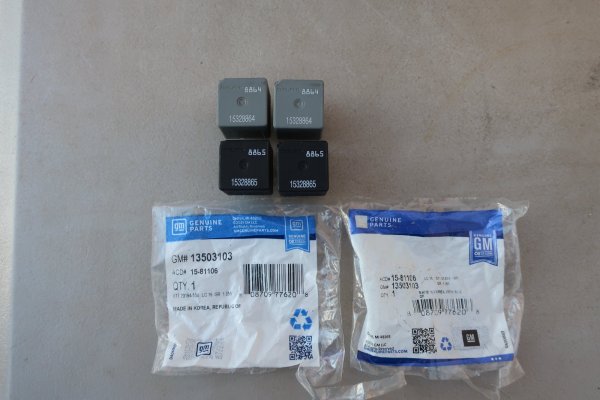
Last thing to do for the cooling system refresh was to replace both the FAN HI and FAN LO relays in the underhood power panel. I got the old relays out and compared them to the new ones.
And realized I screwed up. Old relays were 4-pin. New relays were 5-pin. OK, not a problem. 5th pin is your N.C. 87a. Relays will work just fine.
Wrong. Sockets for fan relays are 4-pin. And I am not so stupid as to cut the 5th pin off the new relays.

Sooo...the FAN CNTRL got a new 5-pin relay. I will order two new correct 4-pin relays and make it right. Luckily, the old relays still work.


2023-12-12 034.JPG
Old relays at top, new relays at bottom. I should have immediately recognized the color difference...


2023-12-12 035.JPG
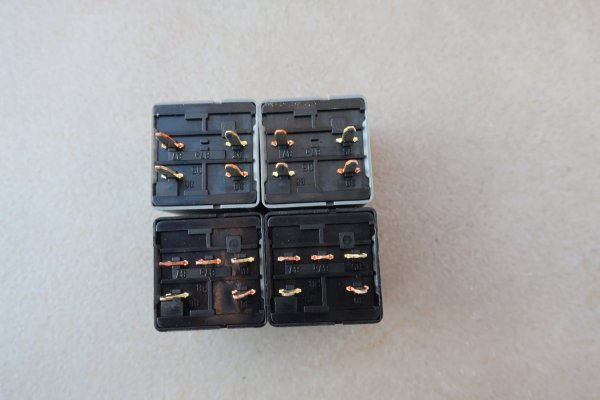
Old relays are 4-pin, new relays are 5-pin.


2023-12-12 036.JPG
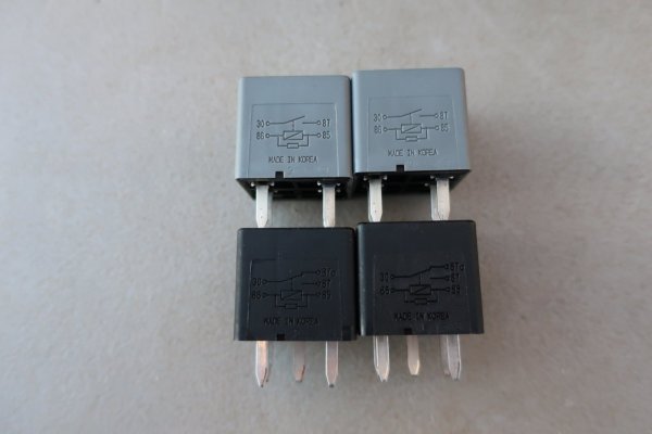
Circuit diagrams show 4 vs 5 pin.


2023-12-12 037.JPG
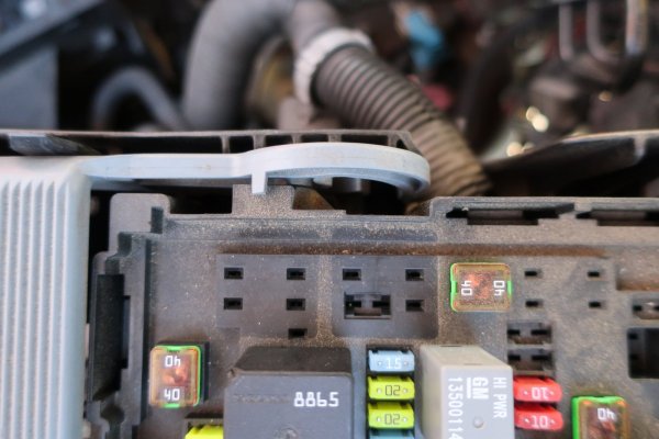
Two empty sockets are for the 4-pin fan relays. FAN HI is on the left and FAN LO is on the right.
Black 8865 5-pin relay just below is the FAN CNTRL. It got replaced.
 
OP
OP
skpyle

skpyle

Full Access Member
Joined
May 15, 2021
Posts
414
Reaction score
1,087
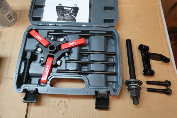
On a side note, the LS balancer/pulley tools I ordered arrived today.

All are Chineseum, but will serve my needs. I did ensure the installer I ordered had a ball thrust bearing.

I am going to pick up an M16 x 2.0 x 60mm socket head bolt at work tomorrow. I have seen the little thrust rods bend with the style of puller I got. In searching 'balancer' here on TYF, I saw several references to using a bolt in place of the thrust rod. Good idea!


2023-12-12 049.JPG
Puller kit at left, installer tool in the middle, and flywheel lock tool at right.
Yes, may only be used twice by me, but I like tools. :gr_grin:
 

iamdub

Full Access Member
Joined
Apr 23, 2016
Posts
20,821
Reaction score
44,944
Location
Li'l Weezyana
Last thing to do for the cooling system refresh was to replace both the FAN HI and FAN LO relays in the underhood power panel. I got the old relays out and compared them to the new ones.
And realized I screwed up. Old relays were 4-pin. New relays were 5-pin. OK, not a problem. 5th pin is your N.C. 87a. Relays will work just fine.
Wrong. Sockets for fan relays are 4-pin. And I am not so stupid as to cut the 5th pin off the new relays.

Sooo...the FAN CNTRL got a new 5-pin relay. I will order two new correct 4-pin relays and make it right. Luckily, the old relays still work.


View attachment 416378
Old relays at top, new relays at bottom. I should have immediately recognized the color difference...


View attachment 416379
Old relays are 4-pin, new relays are 5-pin.


View attachment 416380
Circuit diagrams show 4 vs 5 pin.


View attachment 416381
Two empty sockets are for the 4-pin fan relays. FAN HI is on the left and FAN LO is on the right.
Black 8865 5-pin relay just below is the FAN CNTRL. It got replaced.


Just bend 87a flat. Done. Unless you can and want to return/exchange them.
 
OP
OP
skpyle

skpyle

Full Access Member
Joined
May 15, 2021
Posts
414
Reaction score
1,087
Since I am still waiting on the fuel injectors to return and parts to arrive for the crank pulley, I moved on to the electrical upgrades.

My plan was this:
-220A alternator
-1/0ga (-) battery cable with new terminal
-new RVC sensor
-1/0ga (+) battery cable with new terminal to the mega fuse block on the firewall
-1/0ga (+) battery cable to the alternator (+) power stud
-1/0ga ground cable between the engine and the frame
-onboard battery maintainer
-bluetooth battery monitor


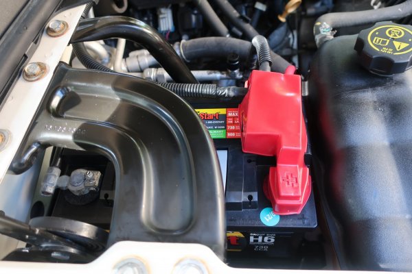
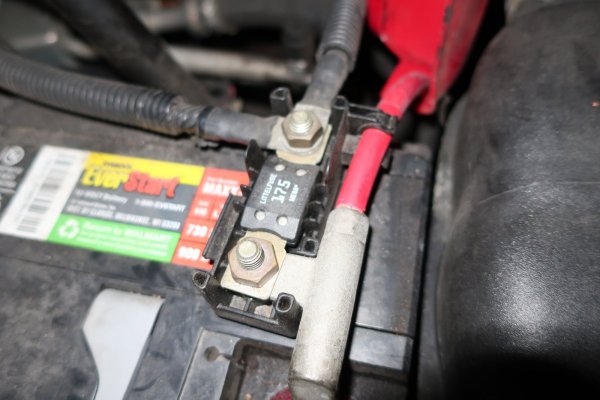
Yeah...that kinda went sideways right off the bat. My 2013 Escalade does not have the mega fuse block on the firewall. It has it directly attached to the (+) battery cable terminal at the battery. If nothing else, means I didn't have to install a new terminal on the cable to the starter.
It did mean I would have to run a 1/0ga (+) battery cable from the battery to the power distribution box on the driver's side fender.


2021-10-14 018.JPG
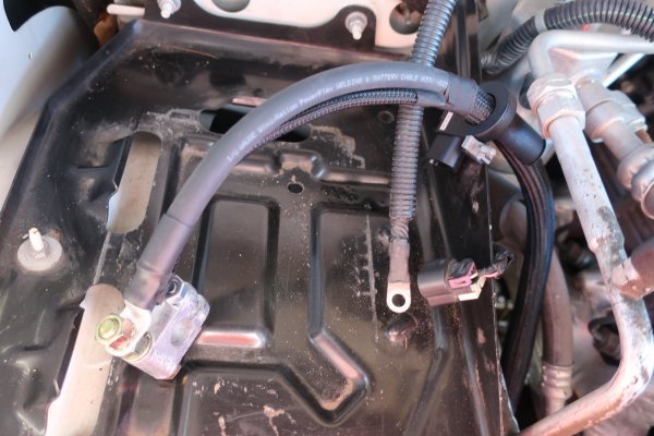
Battery cable configuration on my Escalade.


2023-11-28 010.JPG
Mega fuse block connected directly to the (+) battery cable terminal.


For the sake of (what I thought would be) simplicity, I started with the (-) cables.
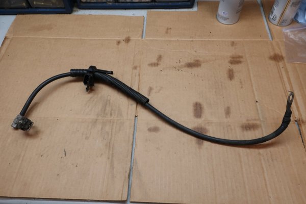
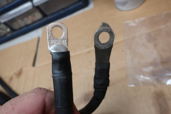
I used the old (-) cable as a guide, cut the new one a couple of inches longer, just because. I crimped 3/8" hole ring terminals at each end and covered them with heat shrink tubing.
The original (-) cable had an additional smaller diameter ground wire going down to the lower front frame. I clipped this off, then put a 3/8" hole ring terminal on it. Both these went to the new (-) terminal on the battery.

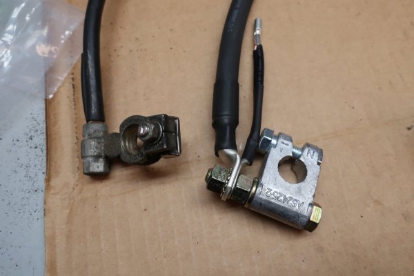
As for the new (-) terminal, I put a longer bolt through it, and a nut on the end to secure it. And act as a spacer. This spaced the (-) cables out far enough to clear the battery case. And I could leave the battery in its original orientation, with the terminals towards the fender.


2023-12-12 019.JPG
Original (-) battery cable with RVC sensor.


2023-12-12 024.JPG
Cylinder head end of new and old (-) battery cables.


2023-12-12 023.JPG
Battery terminal end of old and new (-) battery cables. Yes, new terminal is a touch janky, but it is solid and will work. I have done worse...
 
OP
OP
skpyle

skpyle

Full Access Member
Joined
May 15, 2021
Posts
414
Reaction score
1,087
2023-12-12 025.JPG
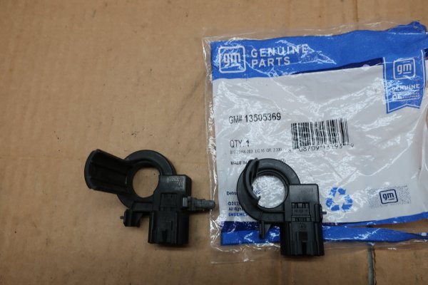
Old RVC sensor at left, new one at right. NOTE: You can install the mounting peg in one of two positions on the RVC sensor. Wanna guess which one I installed it on? Yep, the wrong one. Took awhile for me to figure out why I could not install the sensor like it was in the photos.


2023-12-12 028.JPG
(-) battery cable assembly and RVC sensor. I covered various parts of the cables in braided loom. This replaced the corrugated loom on the original cable.


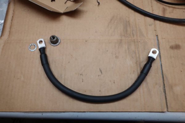
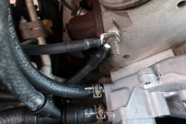
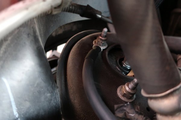
I fabricated a 1/0ga cable with 3/8" hole ring terminals and heat shrink tubing at each end. It ran from the cylinder head ground stud to the outboard upper shock assembly stud on the passenger's side. I put an internal toothed star washer under the ring terminal against the shock mount.


2023-12-12 039.JPG
Short ground cable from cylinder head to shock mount. Note internal star washer and shock mount nut at the left.


2023-12-12 040.JPG
(-) battery cable and short ground cable both go to the front of the passenger's side cylinder head. NOTE: the injector harness ground is not connected to this stud right now because I am installing braided loom on the various harnesses.


2023-12-12 042.JPG
Short ground cable loops around to shock mount stud.
 
OP
OP
skpyle

skpyle

Full Access Member
Joined
May 15, 2021
Posts
414
Reaction score
1,087
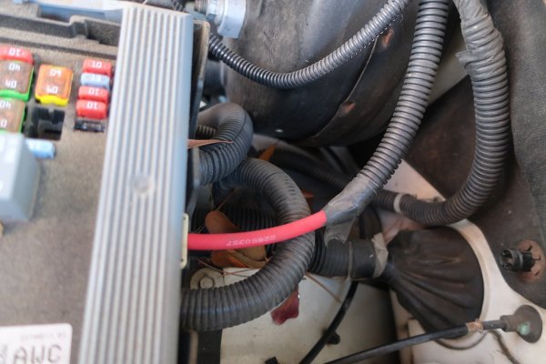
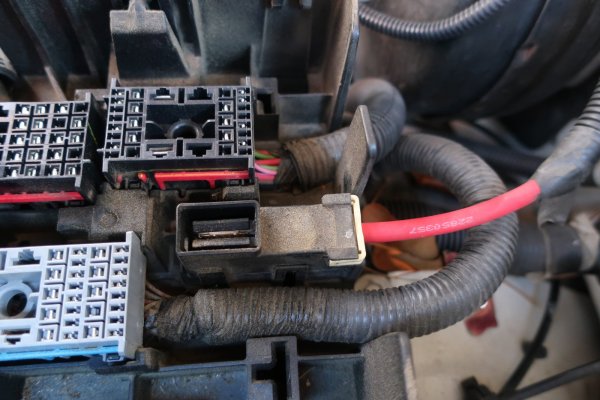
On my 2103 Escalade, the (+) power feed runs from the (+) battery terminal up across the firewall, and down into the power distribution box on the driver's inner fender well. My intent was to replace it with a 1/0ga cable for blessed overkill.

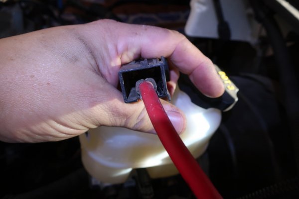
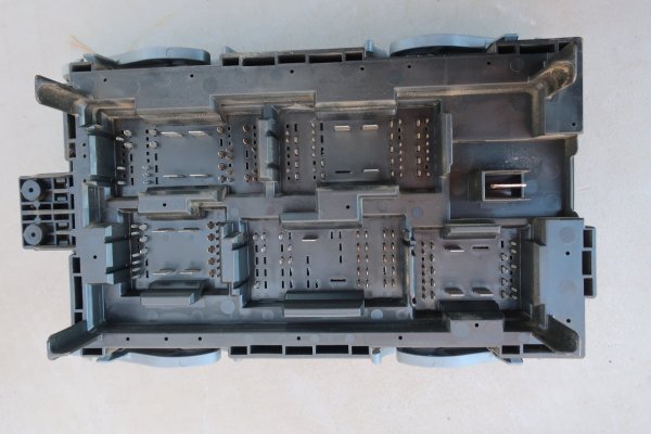
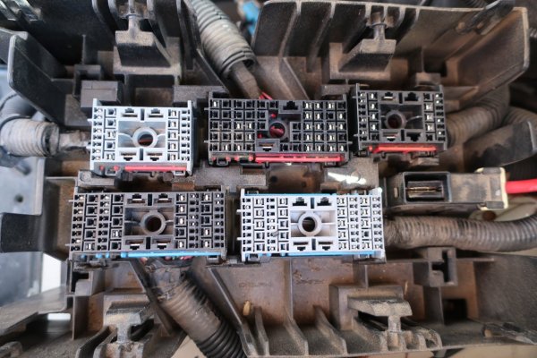
I had to remove the distribution box upper panel to access how the (+) power feed attaches to it. And ran into a wall. This cable is crimped to a specialty terminal that mates with the underside of the distribution box upper panel. Short of cutting the terminal off and making an ugly splice to the 1/0ga cable, I don't know what to do here. Sooo...I left it alone.
In reading articles on the 'Big 3' electrical upgrades, I don't think I read anything about replacing this cable. So I will leave it. If I come up with a better idea, I will address it in the future.

I did take the opportunity to hose down the underside of the distribution box upper panel and the receptacles in the base with contact cleaner. All terminals were nice and clean.


2023-12-12 016.JPG
(+) power feed cable from battery into the distribution box.


2023-12-12 018.JPG
(+) power feed cable runs to a specialty female spade connector in the base of the distribution box.


2023-12-12 033.JPG
Cable is crimped in multiple places. I don't think I could recrimp this onto the 1/0ga cable.


2023-12-12 031.JPG
Underside of the distribution box upper panel.


2023-12-12 030.JPG
Receptacles in the base of the distribution box.
 

Forum statistics

Threads
132,357
Posts
1,866,577
Members
96,979
Latest member
Taetor
Top