2013 Escalade ESV Next BIG adventure: Cooling system refresh, Big 3 Electrical upgrade, Reseal intake, and VLOM mod...

Disclaimer: Links on this page pointing to Amazon, eBay and other sites may include affiliate code. If you click them and make a purchase, we may earn a small commission.

89Suburban

Bull in the china shop
Supporting Member
Joined
Jan 10, 2013
Posts
15,318
Reaction score
42,677
Location
SE PA
Since I am still waiting on the fuel injectors to return and parts to arrive for the crank pulley, I moved on to the electrical upgrades.

My plan was this:
-220A alternator
-1/0ga (-) battery cable with new terminal
-new RVC sensor
-1/0ga (+) battery cable with new terminal to the mega fuse block on the firewall
-1/0ga (+) battery cable to the alternator (+) power stud
-1/0ga ground cable between the engine and the frame
-onboard battery maintainer
-bluetooth battery monitor


Yeah...that kinda went sideways right off the bat. My 2013 Escalade does not have the mega fuse block on the firewall. It has it directly attached to the (+) battery cable terminal at the battery. If nothing else, means I didn't have to install a new terminal on the cable to the starter.
It did mean I would have to run a 1/0ga (+) battery cable from the battery to the power distribution box on the driver's side fender.


View attachment 416401
Battery cable configuration on my Escalade.


View attachment 416402
Mega fuse block connected directly to the (+) battery cable terminal.


For the sake of (what I thought would be) simplicity, I started with the (-) cables.
I used the old (-) cable as a guide, cut the new one a couple of inches longer, just because. I crimped 3/8" hole ring terminals at each end and covered them with heat shrink tubing.
The original (-) cable had an additional smaller diameter ground wire going down to the lower front frame. I clipped this off, then put a 3/8" hole ring terminal on it. Both these went to the new (-) terminal on the battery.

As for the new (-) terminal, I put a longer bolt through it, and a nut on the end to secure it. And act as a spacer. This spaced the (-) cables out far enough to clear the battery case. And I could leave the battery in its original orientation, with the terminals towards the fender.


View attachment 416410
Original (-) battery cable with RVC sensor.


View attachment 416411
Cylinder head end of new and old (-) battery cables.


View attachment 416412
Battery terminal end of old and new (-) battery cables. Yes, new terminal is a touch janky, but it is solid and will work. I have done worse...
This is a great detailed thread an your posts are so entertaining!

Where did you get that red battery post protector? I am in need of one.
 

B-train

Full Access Member
Joined
Sep 12, 2022
Posts
2,309
Reaction score
3,999
Friday, before I laid down for a nap, I tried replacing the locks, O-rings, and spacers for the rear heater core hose quick disconnects.
And failed miserably.


View attachment 416708
Rear heater core hose quick disconnects under the passenger's side rear of the vehicle.


View attachment 416709


View attachment 416710
Could not depress the locking tabs enough for the quick disconnects to release. Did not want to get medieval and break anything.


As far as I can tell, the quick disconnects are the same as the heater hoses that connect to the heater Tees under the hood. However, I could not get the locking tabs to release for love nor money. I tried my fingers, hose pliers, and Knipex pliers. No love. I gave up before I broke something.
I will revisit this in the near future.
In my mind, the O-ring seals and locks are 10 years old. Couldn't hurt to replace them.


View attachment 416711
GM seal and lock kit for rear heater core hose quick disconnects.


View attachment 416712
Spacer goes between the two O-rings. The lock inserts snap into the heater hose quick disconnect housings.
You might be fighting road debris that has settled into the connector. You could try compressed air while pushing it tight towards the core and then wiggle gently. I've fought some of those over the years and just a minute amount of particulate can be a PITA. You could also try spray silicone from the top down and see if that helps loosen stuff up after blowing it out.

Also, I want to say that this has been an EXCELLENT thread to follow. I enjoy your thoroughness and sense of humor. I applaud your efforts and attention to detail.....no matter how many parts it takes. Thank you for this contribution!!!
:happy107:
 
OP
OP
skpyle

skpyle

Full Access Member
Joined
May 15, 2021
Posts
417
Reaction score
1,098
The only thing I can see wrong with this picture is that it’s missing the 8 Rib for the LSA SC :D gj
Yeah...not yet. I'm not saying never, just not yet. :gr_grin:


I replaced my cam phaser when doing my afm delete cam upgrade (not by choice) and it’s not for the faint hearted. The cam pin hole on the back of the phaser is a completely blind fit. It’s easy during the test fit while lining up the timing markers but once you get the chain on you nearly loose all feeling for the pin. It’s pretty nerve wracking to say the least and I had a buddy helping. Also you don’t need to pull the condenser for a cam swap, just the fans and radiator need to be pulled to get the cam in.
Thank you for that insight, I very much appreciate it! VERY good to know that the condenser does not need to come out for a cam swap. Full DOD delete may very well be in my future...


Seth, just as a backup look into gruven parts heater tees and outlets. Those plastic ones suck and are prone to breaking. These may help fo rear as well
Thank you for the heads-up on those, I had forgotten about them.


I installed the GruvenParts https://www.gruvenparts.com/shop-by-car/gm-truck aluminum billet Ts for the front heater 4 yrs ago after a plastic T broke. No regrets ot issues since.
Very good to know, thanks!


This is a great detailed thread an your posts are so entertaining!

Where did you get that red battery post protector? I am in need of one.
You are very welcome! I don't want someone to read my posts and be bored and/or think they are a waste of time. I want my posts to be helpful. If my trials, tribulations, and flat-out mistakes help someone else in the future, then it is worth it.


You might be fighting road debris that has settled into the connector. You could try compressed air while pushing it tight towards the core and then wiggle gently. I've fought some of those over the years and just a minute amount of particulate can be a PITA. You could also try spray silicone from the top down and see if that helps loosen stuff up after blowing it out.

Also, I want to say that this has been an EXCELLENT thread to follow. I enjoy your thoroughness and sense of humor. I applaud your efforts and attention to detail.....no matter how many parts it takes. Thank you for this contribution!!!
:happy107:
Thanks for the tip. I will drag an air tank and aerosol silicone spray out next time I do battle with the rear heater hoses.

I am glad you are enjoying this thread. This kind of thing is my hobby, and I take it way to seriously. :p
 
OP
OP
skpyle

skpyle

Full Access Member
Joined
May 15, 2021
Posts
417
Reaction score
1,098
I continued making progress over the past couple of days. Sort of...

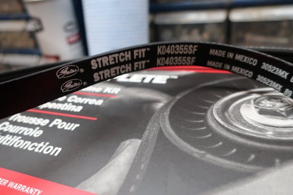
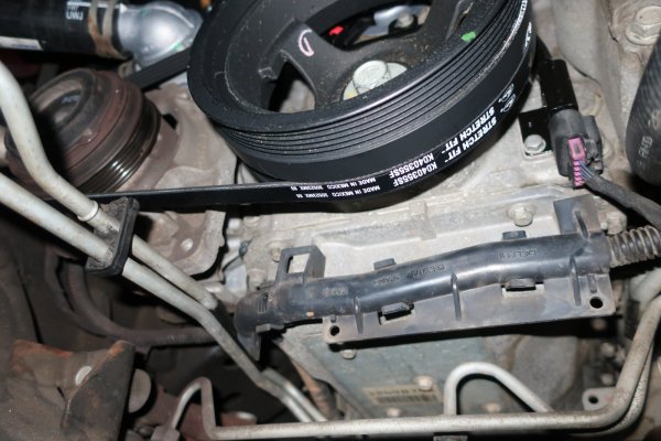
I wrapped up underneath the Escalade by installing the new stretch belt for the AC compressor. New belt went on OK, though of course I got it misaligned one spline on the AC compressor. Had to rotate the crank back and forth a bit to walk the belt back on properly. Like last time, I used the 'secure the belt to the crankshaft pulley with a large zip-tie' trick to install the stretch belt. Worked much better than the installation tool I bought.


2023-12-21 002.JPG
New Gates AC compressor stretch belt. I went with Gates vs ACDelco this time. Last time, the ACDelco kit was full of Gates parts...:rolleyes:


2023-12-21 003.JPG
New stretch belt installed. As mentioned, I had to rotate the crank pulley back and forth a bit to walk the belt back into alignment. I was going to rotate the crank a full revolution to seat the belt. Just because. However....I noticed a couple of funny sounds. Guess who forgot there were rags stuffed in the intake ports and the ports covered in tape...:banghead:
I looked later and noted none of the tape was blown in on any ports. I will be gentle when I remove the rags to ensure none are caught and tear later.


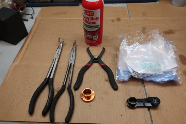
Then, again I tried to remove the rear heater core hose elbow quick disconnects. And again failed. I tried different tools this time. I sprayed aerosol silicone into the top of each quick disconnect. I squeezed until my finger and thumb hurt. To no avail. Tuesday night/Wednesday morning was very bad at work, so I forgot to bring home my long 90 degree needle nosed pliers. In desperation, I tried a couple of fuel/AC line disconnect tools to get a stronger grip on the release tabs. And failed.
I did attempt to protect myself from drowning in coolant. Service manual calls for draining the cooling system. Well...I had just refilled it. And, the rear heater core hose connections are high up on the firewall at the heater Tees. Meaning the entire cooling system should not drain back out there. On the same token, draining the cooling system will not drain the rear heater core and lines. So, I am gambling that the only coolant that will drain from the connections is what is in the rear heater core and the lines.

Regardless, I am working directly UNDER the rear heater core quick disconnects. Each time I fight with the connectors, it is in the back of my mind that I am going to get deluged. I have a clean coolant drain pan nearby. But it is nearby, and will take several seconds to grab and position.
Sooooo...I pretty much crawled into a large garden trash bag. That worked out about as well as expected...


2023-12-21 021.JPG
Tools and materials from failed attempt #2 to remove the rear heater core hose quick disconnects.


Once again giving up on the rear heater core connections, I moved back to the engine compartment.
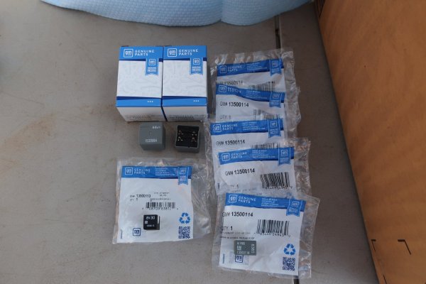
I replaced most of the rest of the relays in the underhood distribution box. I say most, because math is hard and I obviously can't count correctly. I need to order two more relays to be done.
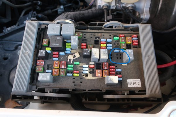
Something I noticed. The label on the underside of the distribution box cover shows a 'FUEL PUMP' relay. Yet, on the distribution box panel, there was no relay. As far as I can tell, this is because the GMT900 platform has a fuel pump control module. I think...


2023-12-21 022.JPG
Correct FAN HI and FAN LO 4-pin relays, as well as two other types of relays for the distribution box. Just not quite enough. The FOG LAMPS and PK LAMPS relays will get changed later. They are not as important as AC COMP and STARTER. :gr_grin:


2023-12-12 017.1.JPG
Label calls for the FUEL PUMP relay to be in the blue circle, but there was no relay.
 
OP
OP
skpyle

skpyle

Full Access Member
Joined
May 15, 2021
Posts
417
Reaction score
1,098
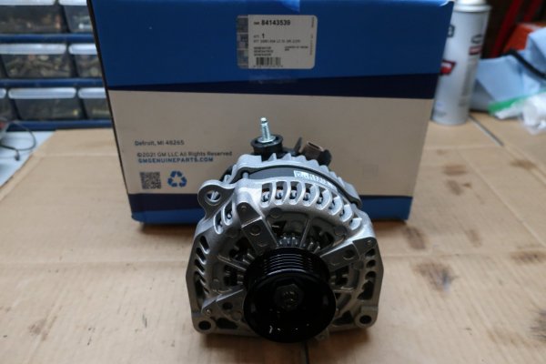
I cannot install it yet, but I wanted to mock up the new alternator to see if there were any hiccups I had to watch out for. The stock DR44 alternator worked just fine. However, it had 153,*** miles on it, and voltage dipped a bit when the fans kicked on. I purchased a new GM 84143539 220A alternator. It is listed for 2015-2020 GM 2500/3500 series trucks and vans.

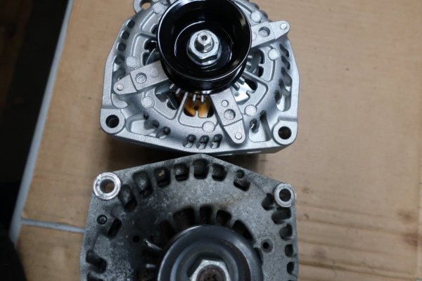
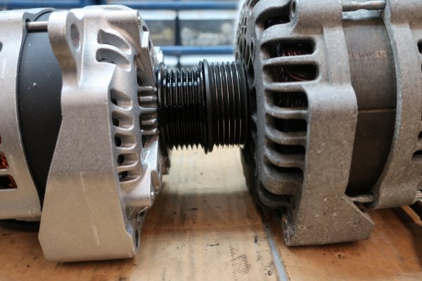
Comparing it to the stock alternator, the two mounting bolt holes are in the same place. The pulleys are the same diameter and in the same centerline position from the mounting holes. Meaning stock serpentine belt will fit just fine.
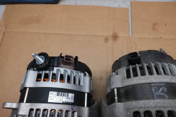
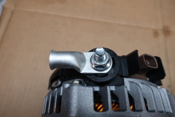
The B+ stud is larger than stock, and clocked differently. Stock is a 6mm stud out the back of the case, at around 2:00 o'clock. New alternator is an 8mm stud out the top of the case, at around 11:00 o'clock. This won't be an issue since I am making a 1/0ga cable from the battery to the alternator.
The electrical receptacle is clocked different as well: 11:00 o'clock stock and 1:00 o'clock new. I don't think this will be an issue as the positions are close and there is a little slack in the plug wiring. We shall see.


2023-12-21 008.JPG
New GM 81443539 220A alternator.


2023-12-21 013.JPG
Mounting holes in the alternator cases are in the same positions. (ignore the belt dust on the old alternator. I never could keep that from happening. New belt, new tensioner, etc...)


2023-12-21 014.JPG
B+ studs and electrical receptacles are clocked differently on the two. Shouldn't be an issue.


2023-12-21 017.JPG
Luckily, I found a flanged M8 nut in my hardware drawers. 1/0ga cable lug with 5/16" hole fits perfectly.


2023-12-21 019.JPG
Pulleys are same diameter and in the same relative position.
 

89Suburban

Bull in the china shop
Supporting Member
Joined
Jan 10, 2013
Posts
15,318
Reaction score
42,677
Location
SE PA
I continued making progress over the past couple of days. Sort of...

I wrapped up underneath the Escalade by installing the new stretch belt for the AC compressor. New belt went on OK, though of course I got it misaligned one spline on the AC compressor. Had to rotate the crank back and forth a bit to walk the belt back on properly. Like last time, I used the 'secure the belt to the crankshaft pulley with a large zip-tie' trick to install the stretch belt. Worked much better than the installation tool I bought.


View attachment 417046
New Gates AC compressor stretch belt. I went with Gates vs ACDelco this time. Last time, the ACDelco kit was full of Gates parts...:rolleyes:


View attachment 417047
New stretch belt installed. As mentioned, I had to rotate the crank pulley back and forth a bit to walk the belt back into alignment. I was going to rotate the crank a full revolution to seat the belt. Just because. However....I noticed a couple of funny sounds. Guess who forgot there were rags stuffed in the intake ports and the ports covered in tape...:banghead:
I looked later and noted none of the tape was blown in on any ports. I will be gentle when I remove the rags to ensure none are caught and tear later.


Then, again I tried to remove the rear heater core hose elbow quick disconnects. And again failed. I tried different tools this time. I sprayed aerosol silicone into the top of each quick disconnect. I squeezed until my finger and thumb hurt. To no avail. Tuesday night/Wednesday morning was very bad at work, so I forgot to bring home my long 90 degree needle nosed pliers. In desperation, I tried a couple of fuel/AC line disconnect tools to get a stronger grip on the release tabs. And failed.
I did attempt to protect myself from drowning in coolant. Service manual calls for draining the cooling system. Well...I had just refilled it. And, the rear heater core hose connections are high up on the firewall at the heater Tees. Meaning the entire cooling system should not drain back out there. On the same token, draining the cooling system will not drain the rear heater core and lines. So, I am gambling that the only coolant that will drain from the connections is what is in the rear heater core and the lines.

Regardless, I am working directly UNDER the rear heater core quick disconnects. Each time I fight with the connectors, it is in the back of my mind that I am going to get deluged. I have a clean coolant drain pan nearby. But it is nearby, and will take several seconds to grab and position.
Sooooo...I pretty much crawled into a large garden trash bag. That worked out about as well as expected...


View attachment 417048
Tools and materials from failed attempt #2 to remove the rear heater core hose quick disconnects.


Once again giving up on the rear heater core connections, I moved back to the engine compartment.
I replaced most of the rest of the relays in the underhood distribution box. I say most, because math is hard and I obviously can't count correctly. I need to order two more relays to be done.
Something I noticed. The label on the underside of the distribution box cover shows a 'FUEL PUMP' relay. Yet, on the distribution box panel, there was no relay. As far as I can tell, this is because the GMT900 platform has a fuel pump control module. I think...


View attachment 417049
Correct FAN HI and FAN LO 4-pin relays, as well as two other types of relays for the distribution box. Just not quite enough. The FOG LAMPS and PK LAMPS relays will get changed later. They are not as important as AC COMP and STARTER. :gr_grin:


View attachment 417050
Label calls for the FUEL PUMP relay to be in the blue circle, but there was no relay.


Hey amigo, get one of these. Use the long skinny hose to stick down one of the rear feed pipes and suck that coolant out completely. I use this thing constantly for many repairs. When I replaced my radiator I used this to remove the coolant top to bottom as things were being disassembled. Did not need a drain pan at all. VERY handy tool.

 
OP
OP
skpyle

skpyle

Full Access Member
Joined
May 15, 2021
Posts
417
Reaction score
1,098
Hey amigo, get one of these. Use the long skinny hose to stick down one of the rear feed pipes and suck that coolant out completely. I use this thing constantly for many repairs. When I replaced my radiator I used this to remove the coolant top to bottom as things were being disassembled. Did not need a drain pan at all. VERY handy tool.


Sweet!
I bought this years ago:

https://www.northerntool.com/produc...e1SOG0wJel7tnYB1SPYt1294rg_XDpK7qmYa0m19OBekg

I think it will serve the same purpose.

Thanks!
 
OP
OP
skpyle

skpyle

Full Access Member
Joined
May 15, 2021
Posts
417
Reaction score
1,098
Finished my day in the engine bay.

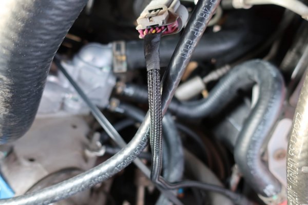
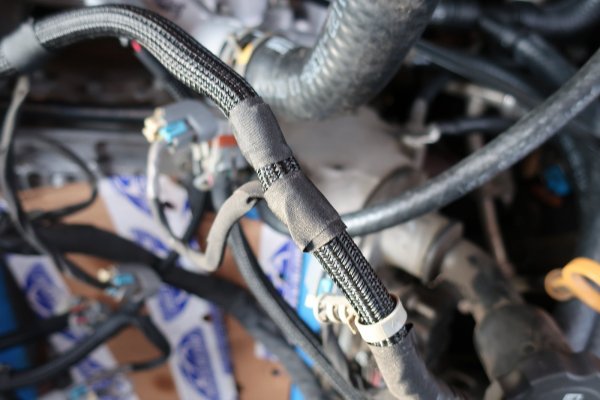
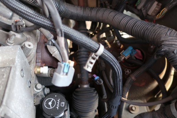
The plastic corrugated split tubing loom that covered the engine bay wiring harness was deteriorated in many places. To the point of being missing. I removed and/or cut away all the bad loom. I got a tip from a fellow here at TYF a couple of years ago: plastic braided split loom. I had bought 1". 3/4", 1/2", 3/8", and 1/4", as well as several rolls of sealing tape.

Go to post #129 in this thread:
https://www.tahoeyukonforum.com/thr...cle-refurbishment.130866/page-13#post-1651580

One by one, I went through the harness runs and fitted the new braided loom on each. I used sealing tape at each end. And wherever there was a breakout.
Overall, I am very pleased with the result! This was a good idea Chooko!!!


2023-12-21 024.JPG


2023-12-21 025.JPG


2023-12-21 026.JPG
New braided split loom looks much better. I did not do the entire harness. The larger main sections were intact. I just taped the joints between the old and new tubing. Also, smaller break out wires were wrapped in a heavy fabric tape. Such as the fuel injector wires or the coolant temp sensor plug. All of them were in good condition, so I didn't cover them.


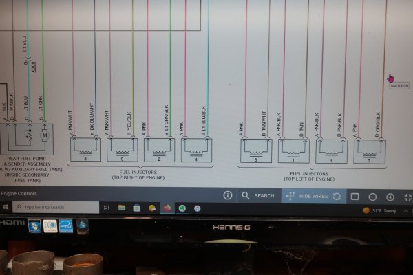
Had to fix a possible screw-up. Again rereading the service manual instructions for intake manifold R&R, it talked about 'labeling the fuel injector connectors.' Uh-oh. I didn't do that. I had photos. And I was 'pretty sure' I knew which plug went where.
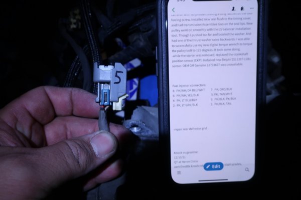
To be sure, I went to the Interactive Color Wiring Diagram - non OE in AllData. I was able to determine what color wires went to each fuel injector connector. Then matched it up on my connectors. Sharpie took care of the rest.
Much better.


2023-12-21 028.JPG
Color wiring diagram of the fuel injectors from AllData.


2023-12-21 027.JPG
I put notes in my phone, then compared them to the injector wiring at the Escalade.


I am now at a stopping point. I am still waiting for the fuel injectors to return. :(
Once they are back, the intake manifold gets reassembled and reinstalled.
Engine bay wiring harness gets routed and reconnected.
Serpentine belt system gets reinstalled.
Any other little details.

Then start this sucker!!!
 

89Suburban

Bull in the china shop
Supporting Member
Joined
Jan 10, 2013
Posts
15,318
Reaction score
42,677
Location
SE PA
Finished my day in the engine bay.

The plastic corrugated split tubing loom that covered the engine bay wiring harness was deteriorated in many places. To the point of being missing. I removed and/or cut away all the bad loom. I got a tip from a fellow here at TYF a couple of years ago: plastic braided split loom. I had bought 1". 3/4", 1/2", 3/8", and 1/4", as well as several rolls of sealing tape.

Go to post #129 in this thread:
https://www.tahoeyukonforum.com/thr...cle-refurbishment.130866/page-13#post-1651580

One by one, I went through the harness runs and fitted the new braided loom on each. I used sealing tape at each end. And wherever there was a breakout.
Overall, I am very pleased with the result! This was a good idea Chooko!!!


View attachment 417066


View attachment 417067


View attachment 417068
New braided split loom looks much better. I did not do the entire harness. The larger main sections were intact. I just taped the joints between the old and new tubing. Also, smaller break out wires were wrapped in a heavy fabric tape. Such as the fuel injector wires or the coolant temp sensor plug. All of them were in good condition, so I didn't cover them.


Had to fix a possible screw-up. Again rereading the service manual instructions for intake manifold R&R, it talked about 'labeling the fuel injector connectors.' Uh-oh. I didn't do that. I had photos. And I was 'pretty sure' I knew which plug went where.
To be sure, I went to the Interactive Color Wiring Diagram - non OE in AllData. I was able to determine what color wires went to each fuel injector connector. Then matched it up on my connectors. Sharpie took care of the rest.
Much better.


View attachment 417069
Color wiring diagram of the fuel injectors from AllData.


View attachment 417070
I put notes in my phone, then compared them to the injector wiring at the Escalade.


I am now at a stopping point. I am still waiting for the fuel injectors to return. :(
Once they are back, the intake manifold gets reassembled and reinstalled.
Engine bay wiring harness gets routed and reconnected.
Serpentine belt system gets reinstalled.
Any other little details.

Then start this sucker!!!
Looks good. Hopefully the taped ends don't put too much stress on the wiring where it enters the plug.

I am curious, on the wire harness where it connects to the throttle body. Did you replace that loom as well? Did you notice any kind of splicing in that area of that pigtail? Or differences in the color coding of the wire sheaths?
 
Top