Modded
That Guy
- Joined
- May 3, 2009
- Posts
- 6,942
- Reaction score
- 107
NNBS Upgrade Write Up – BIG 3 and Audio System Install
I decided to make a write up that is easy to understand about upgrading the stock electrical system on the NNBS. I did the BIG 3 and Ran some wires for the new Audio system I am in the process of building. I tried to make it as step by step as possible so it VERY LONG.
In the BIG 3 wiring upgrade the positive battery wire to the alternator needs to be upgraded to a thicker gauge. The negative battery terminal should also be grounded directly to the chassis with the same thick gauge. You will also need to upgrade the engine to chassis ground in the same thick gauge. On the NNBS, the negative battery terminal is grounded to the engine block only, not the chassis. In the write up I change that and ground it to the chassis while also adding a separate ground wire from the chassis to engine block.
As for the positive wiring, the factory positive terminal has two wires coming out from it. One goes to somewhere under the engine block. The other is short and goes to the factory fused distribution block. The block then separates this wire into two thinner wires which go to the engine fuse box and alternator.
I felt to do this big 3 correctly it would be good to still utilize the factory distribution block. So I ran a short length of 0 gauge wire from the battery to the fuse box, then a longer cut of 0 gauge from the fused portion of the distribution block to the alternator. I left the dist/ block to engine bay fuse box wire intact. I then ran the other wire that use to go to the stock positive terminal to the bottom unfused potion of the distribution block.
I will not make out a list of parts I used. Instead, I will cover/list the parts as the steps go on.
On to the Write Up:
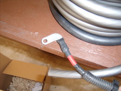
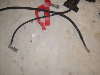
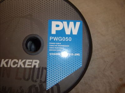
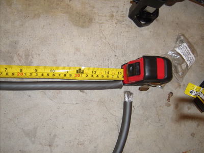
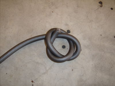
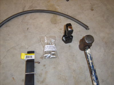
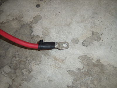
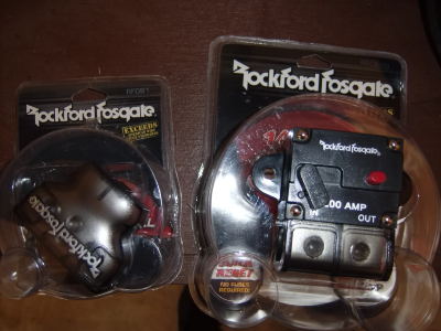
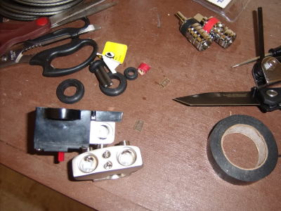
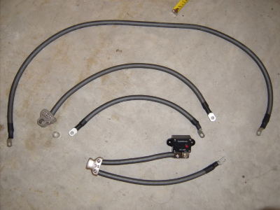
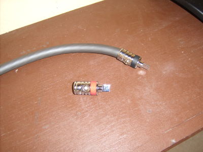
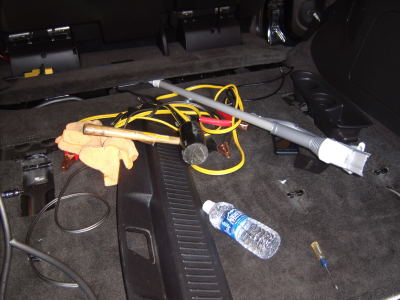
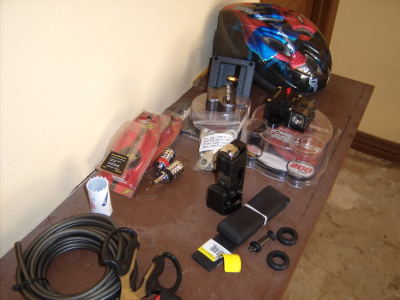
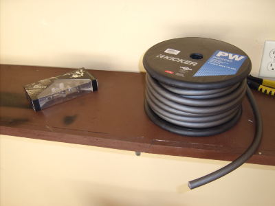
I gathered all the parts together for the build in the pic below. The retailer I bought the spool (50 feet) of Kicker Hyperflex 0 Gauge wire from through in a set of Kicker headphones for free.
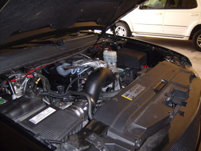
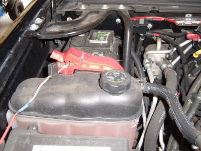
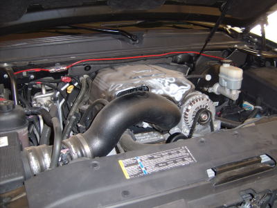
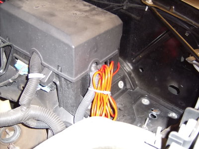
I started with a pic of my engine bay to show the relative locations and stock set up. I also have an 8 gauge wiring kit for my old audio setup in there. Ignore it because if you do not have an aftermarket audio system you will not have a wire like the red one I have running along the top. I also have the power wire for my HIDs the yellow one) showing. Ignore that also if you do not have HIDs. And yeah I know my engine bay is dusty. I have been meaning to wash it off lately but haven’t in about three months.
You will need to remove the battery next. Disconnect the positive and negative terminals with a 10mm deep socket and a ratchet. Then you will have to remove the fender elbow above the battery so that you can get the battery out. You will need a 12mm socket for this. There are four bolts that hold it in.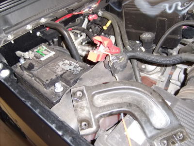
Then remove the battery base clamp with a 13mm deep socket and an extension. I pointed to beside it with the socket.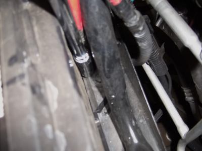
This is what the clamp looks like after removal.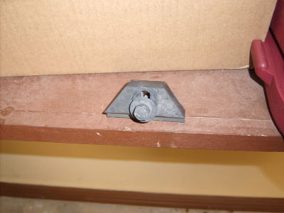
Now after the battery is out it will look like this.
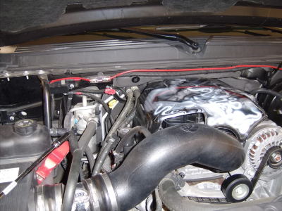
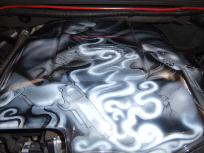
For those wondering, the engine cover has two girls airbrushed on it.
---------- Post added at 01:13 AM ---------- Previous post was at 01:12 AM ----------
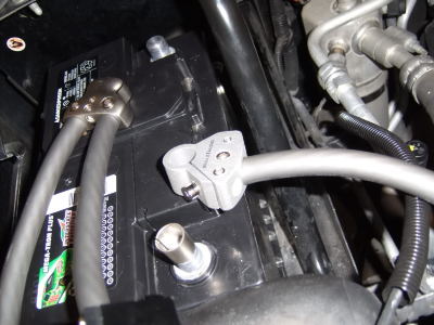
[/COLOR]After I got the battery out I wiped it down and reinstalled it in a flipped position. So now the terminals face in, not out. You will have to do this if you have the stock battery (or an aftermarket replacement battery with the same casing as the stock one) because the terminals are recessed. It is impossible to install aftermarket battery terminals (which you need for such a build) while the battery is in the stock position due to these recessed terminals. This is what it looks like flipped and cleaned up.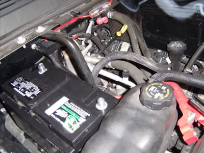
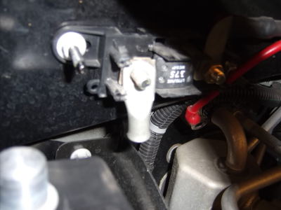
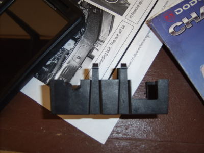
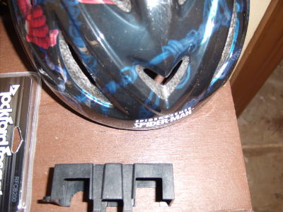
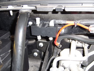
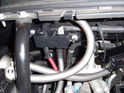
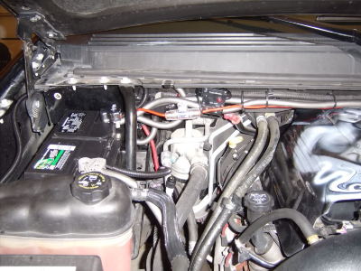
Next, you need to locate the stock fused distribution block. It is pictured in the last step to the immediate top right of the battery. Remove the cover by squeezing the sides of the cover. After removal it looks like this.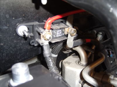
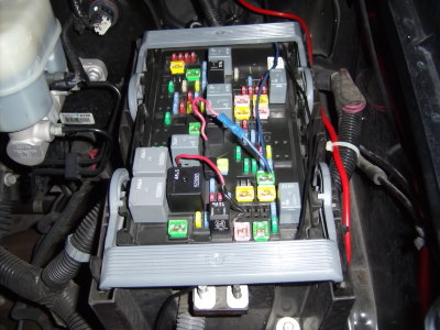
Again, ignore my amp connection to the distribution block. BTW, if you are ever installing a minor system (500w RMS and under) get your power before the dist. block fuse, not after. This prevents a possible electrical cripple if something shorts out. Also fuse your amp wire right before it gets to the front portion of the distribution block like I did to mine.
Next, remove the red plastic OE positive battery terminal wiring cover. You can use a flat screw driver to do this. Just slip it in the sides and pop them up.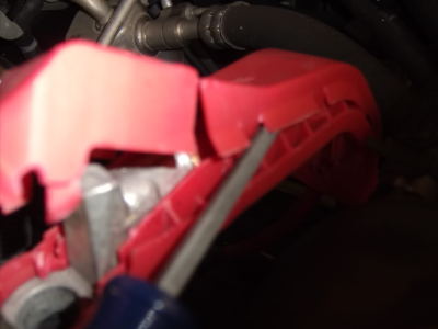
It will look like this when you get the top of the cover off.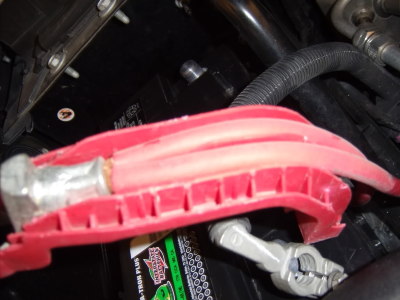
It will then look like this with the whole thing off.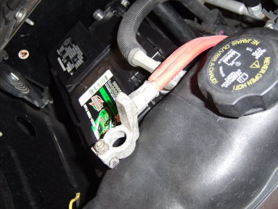
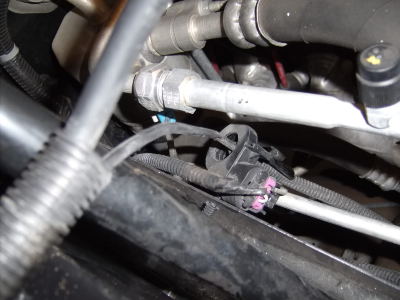
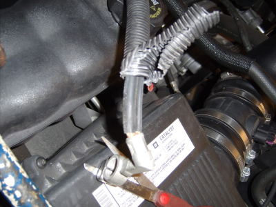
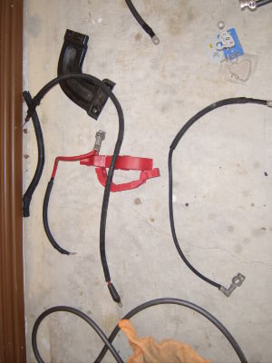
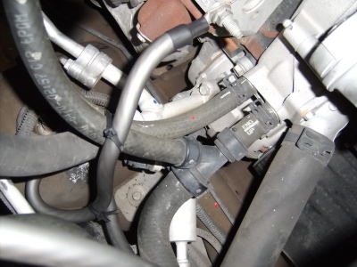
Now you will need to follow the two positive terminal wires. One goes to the fused distribution block. The other goes to the underside of the engine bay. Cut the wire that goes to under the engine bay from the factory terminal. It is crimped so well from the factory it cannot be pulled from the terminal. It looks like this after being cut with a metal snip. Exercise caution when using these snips because they are sharp enough to seriously injure you.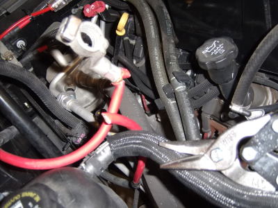
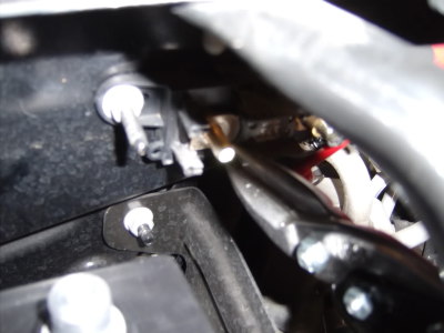
I then removed the other positive terminal wire from the distribution block with a 13mm deep socket. Then you can completely remove the stock positive terminal wiring.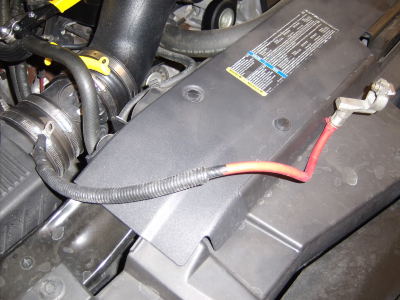
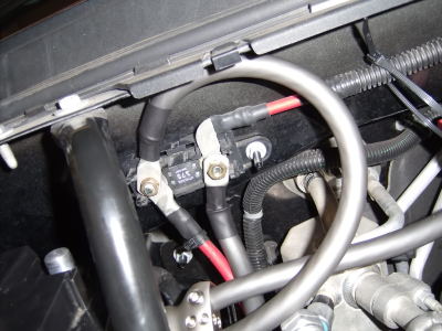
The terminal looks like this after removing the wire from the above pic.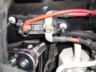
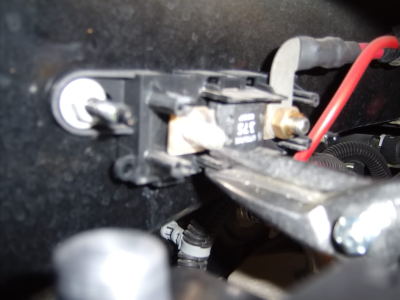
Again, ignore the red aftermarket wire. Now, use the last pic to remove the connector that goes from the distribution block to the alternator. It is on the bottom part of the fused block and you will need a 13mm deep socket for removal.
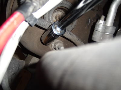
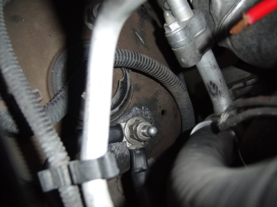
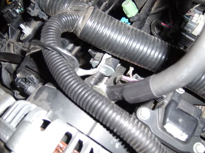
The two positive wires after the distribution block fuse go to the engine bay fuse box and alternator. The wire at the back of the alt. that goes to the distribution block looks like this.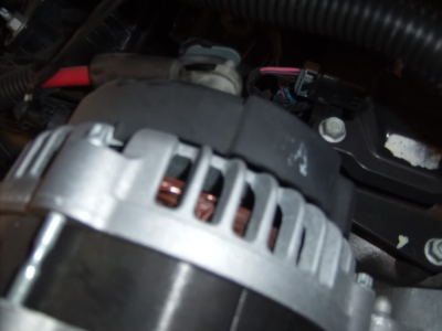
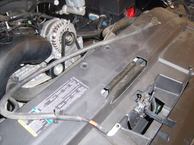
After removing the wire connector from the dist. block, remove the stock engine cover by pulling the front up gently, then out. It will look like this after it is out.
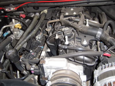
I decided to make a write up that is easy to understand about upgrading the stock electrical system on the NNBS. I did the BIG 3 and Ran some wires for the new Audio system I am in the process of building. I tried to make it as step by step as possible so it VERY LONG.
In the BIG 3 wiring upgrade the positive battery wire to the alternator needs to be upgraded to a thicker gauge. The negative battery terminal should also be grounded directly to the chassis with the same thick gauge. You will also need to upgrade the engine to chassis ground in the same thick gauge. On the NNBS, the negative battery terminal is grounded to the engine block only, not the chassis. In the write up I change that and ground it to the chassis while also adding a separate ground wire from the chassis to engine block.
As for the positive wiring, the factory positive terminal has two wires coming out from it. One goes to somewhere under the engine block. The other is short and goes to the factory fused distribution block. The block then separates this wire into two thinner wires which go to the engine fuse box and alternator.
I felt to do this big 3 correctly it would be good to still utilize the factory distribution block. So I ran a short length of 0 gauge wire from the battery to the fuse box, then a longer cut of 0 gauge from the fused portion of the distribution block to the alternator. I left the dist/ block to engine bay fuse box wire intact. I then ran the other wire that use to go to the stock positive terminal to the bottom unfused potion of the distribution block.
I will not make out a list of parts I used. Instead, I will cover/list the parts as the steps go on.
On to the Write Up:
I gathered all the parts together for the build in the pic below. The retailer I bought the spool (50 feet) of Kicker Hyperflex 0 Gauge wire from through in a set of Kicker headphones for free.


I started with a pic of my engine bay to show the relative locations and stock set up. I also have an 8 gauge wiring kit for my old audio setup in there. Ignore it because if you do not have an aftermarket audio system you will not have a wire like the red one I have running along the top. I also have the power wire for my HIDs the yellow one) showing. Ignore that also if you do not have HIDs. And yeah I know my engine bay is dusty. I have been meaning to wash it off lately but haven’t in about three months.


You will need to remove the battery next. Disconnect the positive and negative terminals with a 10mm deep socket and a ratchet. Then you will have to remove the fender elbow above the battery so that you can get the battery out. You will need a 12mm socket for this. There are four bolts that hold it in.

Then remove the battery base clamp with a 13mm deep socket and an extension. I pointed to beside it with the socket.

This is what the clamp looks like after removal.

Now after the battery is out it will look like this.

For those wondering, the engine cover has two girls airbrushed on it.

---------- Post added at 01:13 AM ---------- Previous post was at 01:12 AM ----------
[/COLOR]After I got the battery out I wiped it down and reinstalled it in a flipped position. So now the terminals face in, not out. You will have to do this if you have the stock battery (or an aftermarket replacement battery with the same casing as the stock one) because the terminals are recessed. It is impossible to install aftermarket battery terminals (which you need for such a build) while the battery is in the stock position due to these recessed terminals. This is what it looks like flipped and cleaned up.

Next, you need to locate the stock fused distribution block. It is pictured in the last step to the immediate top right of the battery. Remove the cover by squeezing the sides of the cover. After removal it looks like this.

Again, ignore my amp connection to the distribution block. BTW, if you are ever installing a minor system (500w RMS and under) get your power before the dist. block fuse, not after. This prevents a possible electrical cripple if something shorts out. Also fuse your amp wire right before it gets to the front portion of the distribution block like I did to mine.
Next, remove the red plastic OE positive battery terminal wiring cover. You can use a flat screw driver to do this. Just slip it in the sides and pop them up.

It will look like this when you get the top of the cover off.

It will then look like this with the whole thing off.

Now you will need to follow the two positive terminal wires. One goes to the fused distribution block. The other goes to the underside of the engine bay. Cut the wire that goes to under the engine bay from the factory terminal. It is crimped so well from the factory it cannot be pulled from the terminal. It looks like this after being cut with a metal snip. Exercise caution when using these snips because they are sharp enough to seriously injure you.

I then removed the other positive terminal wire from the distribution block with a 13mm deep socket. Then you can completely remove the stock positive terminal wiring.

The terminal looks like this after removing the wire from the above pic.

Again, ignore the red aftermarket wire. Now, use the last pic to remove the connector that goes from the distribution block to the alternator. It is on the bottom part of the fused block and you will need a 13mm deep socket for removal.
The two positive wires after the distribution block fuse go to the engine bay fuse box and alternator. The wire at the back of the alt. that goes to the distribution block looks like this.

After removing the wire connector from the dist. block, remove the stock engine cover by pulling the front up gently, then out. It will look like this after it is out.

Last edited:

