Head gasket replacement checklist

Disclaimer: Links on this page pointing to Amazon, eBay and other sites may include affiliate code. If you click them and make a purchase, we may earn a small commission.

Matahoe

Full Access Member
Joined
Jan 27, 2016
Posts
445
Reaction score
164
Location
Grand Rapids, Michigan
Can anyone who has first hand exp. say approximately how much time to R&R the head gaskets on both sided takes start to finish? I am experienced but the time differs on separate makes..etc.

I have all required tools and replacement parts already on hand. I have also contacted my local machine shop and they assure me a quick 2 day turnaround with the head clean and crack check. I need to be speedy as its my only vehicle and I have the kids during the day. Thanks!
 

randeez

Full Access Member
Joined
Sep 29, 2017
Posts
7,444
Reaction score
23,679
Location
south florida
/\ that would be pretty accurate, but nothing ever goes as planned for me. broken exhaust bolts, stripped threads, broken sensors etc. with the downtime for getting the heads cleaned and checked you should be able to find anything you need in that time.
 

Chubbs

Full Access Member
Joined
Jun 24, 2017
Posts
634
Reaction score
391
I've had top end gasket kits sealed in the package come up short on quantity that held me up. You are supposed to get a cleaning tap, run all of the head bolt holes in the block, clean & degrease, then hit with compressed air holding a lint-free cloth over the area.


Cylinder Head Replacement - Left Side

  • Tools Required
  • J 36660-A | J 36660-A Torque Angle Meter

  • J 42385-200 | J 42385-200 Thread Repair Kit
Removal Procedure
  1. Remove the generator bracket. Refer to Generator Replacement (4.8L, 5.3L, and 6.0L Engines)| Generator Replacement (8.1L Engine) in Engine Electrical.

  2. Remove the intake manifold. Refer to Intake Manifold Replacement.

  3. Remove the coolant air bleed pipe. Refer to Engine Coolant Air Bleed Pipe Replacement (4.8L, 5.3L, and 6.0L Engines) in Engine Cooling.

  4. Remove the left exhaust manifold. Refer to Exhaust Manifold Replacement - Left Side (4.8L, 5.3L, and 6.0L Engines) | Exhaust Manifold Replacement - Left Side (8.1L Engine) in Engine Exhaust.

  5. Remove the pushrods. Refer to Valve Rocker Arm and Push Rod Replacement.

  6. 832957.gif


    Click to Enlarge


    NOTE
    Important

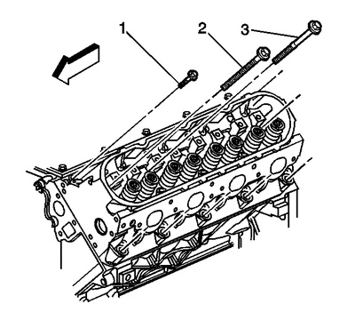
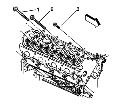
    The cylinder head bolts are NOT reusable.


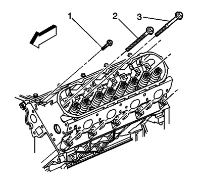
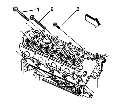
    Remove and discard the cylinder head bolts (1, 2, 3).


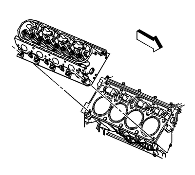
  7. 832958.gif


    Click to Enlarge


    NOTE
    Notice

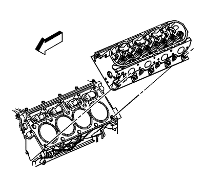
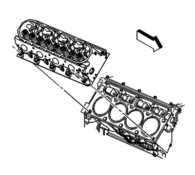
    After removal, place the cylinder head on 2 wood blocks in order to prevent damage to the sealing surfaces.


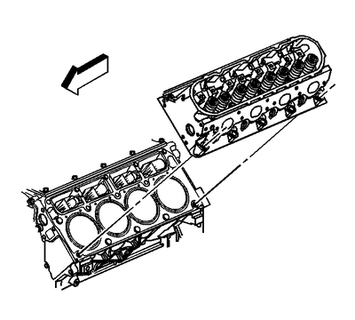
    Remove the cylinder head.

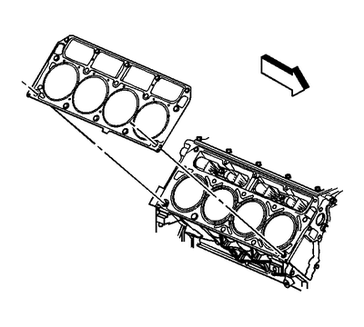
  8. 832962.gif


    Click to Enlarge
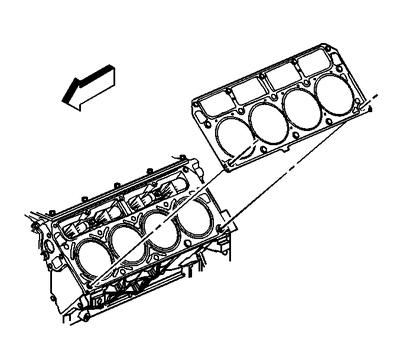
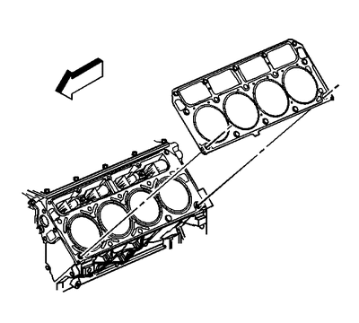
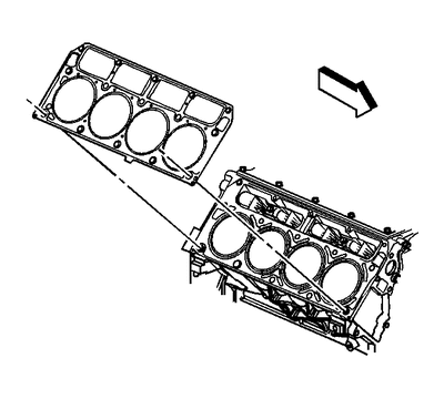
    Remove and discard the cylinder head gasket.

  9. If required, clean and inspect the cylinder head. Refer to Cylinder Head Cleaning and Inspection.
Installation Procedure


CAUTION
Caution

Wear safety glasses in order to avoid eye damage.


NOTE
Notice

Clean all dirt, debris, and coolant from the engine block cylinder head bolt holes. Failure to remove all foreign material may result in damaged threads, improperly tightened fasteners or damage to components.


NOTE
Important

  • Do not reuse the cylinder head bolts. Install NEW cylinder head bolts during assembly.

  • Do not use any type of sealant on the cylinder head gasket, unless specified.

  • The cylinder head gaskets must be installed in the proper direction and position.


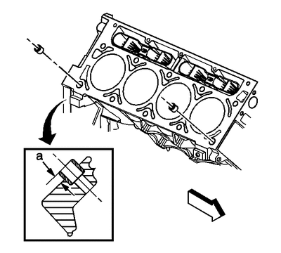
  1. 832969.gif


    Click to Enlarge
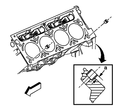
    Clean the engine block cylinder head bolt holes, if required.

    Thread repair tool J 42385-107, found in J 42385-200 | J 42385-200 may be used to clean the threads of old threadlocking material.

  2. Use spray cleaner GM P/N 12346139, P/N 12377981, (Canadian P/N 10953463) or equivalent into the hole.

  3. Clean the cylinder head bolt holes with compressed air.

  4. Check the cylinder head locating pins for proper installation, location (a) 8.3 mm (0.327 in).

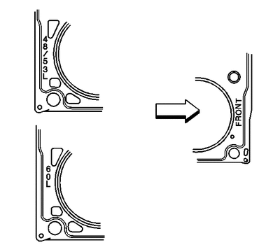
  5. 832963.gif


    Click to Enlarge
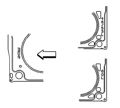
    When properly installed, with FRONT on the left side, the tab on the cylinder head gasket should be located left of center or closer to the front of the engine.

  6. 832962.gif


    Click to Enlarge
    Install the NEW cylinder head gasket.

  7. 832958.gif


    Click to Enlarge
    Install the cylinder head.

  8. 832957.gif


    Click to Enlarge
    Install NEW cylinder head bolts (1, 2, 3).

  9. 832971.gif


    Click to Enlarge


    NOTE
    Notice

    Refer to Fastener Notice | Fastener Notice | Fastener Notice in Cautions and Notices.


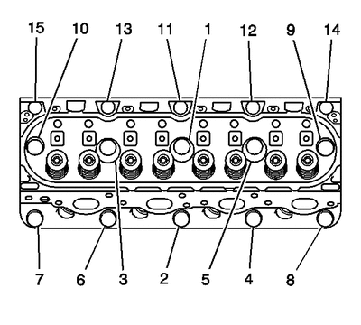
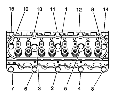
    Tighten the cylinder head bolts.


    Tighten
    1. Tighten the M11 bolts a first pass in sequence to 30 N·m (22 lb ft).

    2. Tighten the M11 bolts a second pass in sequence to 90 degrees using J 36660-A | J 36660-A.

    3. Tighten the M11 bolts (1, 2, 3, 4, 5, 6, 7, 8) to 90 degrees and the M11 bolts (9 and 10) to 50 degrees a final pass in sequence using J 36660-A | J 36660-A.

    4. Tighten the M8 bolts (11, 12, 13, 14, 15) to 30 N·m (22 lb ft). Begin with the center bolt (11) and alternating side-to-side, work outward tightening all of the bolts.
  10. Install the pushrods. Refer to Valve Rocker Arm and Push Rod Replacement.

  11. Install the left exhaust manifold. Refer to Exhaust Manifold Replacement - Left Side (4.8L, 5.3L, and 6.0L Engines) | Exhaust Manifold Replacement - Left Side (8.1L Engine) in Engine Exhaust.

  12. Install the coolant air bleed pipe. Refer to Engine Coolant Air Bleed Pipe Replacement (4.8L, 5.3L, and 6.0L Engines) in Engine Cooling.

  13. Install the intake manifold. Refer to Intake Manifold Replacement.

  14. Install the generator bracket. Refer to Generator Replacement (4.8L, 5.3L, and 6.0L Engines) | Generator Replacement (8.1L Engine) in Engine Electrical.
 

Chubbs

Full Access Member
Joined
Jun 24, 2017
Posts
634
Reaction score
391
Cylinder Head, right side


  • Tools Required
  • J 36660-A | J 36660-A Torque Angle Meter

  • J 42385-200 | J 42385-200 Thread Repair Kit
Removal Procedure
  1. Remove the oil level indicator. Refer to Oil Level Indicator Tube Replacement.

  2. Remove the intake manifold. Refer to Intake Manifold Replacement.

  3. Remove the coolant air bleed pipe. Refer to Engine Coolant Air Bleed Pipe Replacement (4.8L, 5.3L, and 6.0L Engines) in Engine Cooling.

  4. Remove the right exhaust manifold. Refer to Exhaust Manifold Replacement - Right Side (4.8L, 5.3L, and 6.0L Engines) | Exhaust Manifold Replacement - Right Side (8.1L Engine) in Engine Exhaust.

  5. Remove the pushrods. Refer to Valve Rocker Arm and Push Rod Replacement.

  6. 832959.gif


    Click to Enlarge


    NOTE
    Important

    The cylinder head bolts are NOT reusable.


    Remove and discard the cylinder head bolts (1, 2, 3).

  7. 832960.gif


    Click to Enlarge


    NOTE
    Notice

    After removal, place the cylinder head on 2 wood blocks in order to prevent damage to the sealing surfaces.


    Remove the cylinder head.

  8. 832965.gif


    Click to Enlarge
    Remove and discard the cylinder head gasket.

  9. If required, clean and inspect the cylinder head. Refer to Cylinder Head Cleaning and Inspection.
Installation Procedure


CAUTION
Caution

Wear safety glasses in order to avoid eye damage.


NOTE
Notice

Clean all dirt, debris, and coolant from the engine block cylinder head bolt holes. Failure to remove all foreign material may result in damaged threads, improperly tightened fasteners or damage to components.


NOTE
Important

  • Do not reuse the cylinder head bolts. Install NEW cylinder head bolts during assembly.

  • Do not use any type of sealant on the cylinder head gasket, unless specified.

  • The cylinder head gaskets must be installed in the proper direction and position.


  1. 832970.gif


    Click to Enlarge
    Clean the engine block cylinder head bolt holes, if required.

    Thread repair tool J 42385-107, found in J 42385-200 | J 42385-200 may be used to clean the threads of old threadlocking material.

  2. Use spray cleaner GM P/N 12346139, P/N 12377981, (Canadian P/N 10953463) or equivalent into the hole.

  3. Clean the cylinder head bolt holes with compressed air.

  4. Check the cylinder head locating pins for proper installation, location (a) 8.3 mm (0.327 in).

  5. 832967.gif


    Click to Enlarge
    When properly installed, with FRONT on the right side, the tab on the cylinder head gasket should be located right of center or closer to the front of the engine.

  6. 832965.gif


    Click to Enlarge
    Install the NEW cylinder head gasket.

  7. 832960.gif


    Click to Enlarge
    Install the cylinder head.

  8. 832959.gif


    Click to Enlarge
    Install the NEW cylinder head bolts.

  9. 832971.gif


    Click to Enlarge


    NOTE
    Notice

    Refer to Fastener Notice | Fastener Notice | Fastener Notice in Cautions and Notices.


    Tighten the cylinder head bolts.


    Tighten
    1. Tighten the M11 bolts a first pass in sequence to 30 N·m (22 lb ft).

    2. Tighten the M11 bolts a second pass in sequence to 90 degrees using J 36660-A | J 36660-A.

    3. Tighten the M11 bolts (1, 2, 3, 4, 5, 6, 7, 8) to 90 degrees and the M11 bolts (9 and 10) to 50 degrees a final pass in sequence using J 36660-A | J 36660-A.

    4. Tighten the M8 bolts (11, 12, 13, 14, 15) to 30 N·m (22 lb ft). Begin with the center bolt (11) and alternating side-to-side, work outward tightening all of the bolts.
  10. Install the pushrods. Refer to Valve Rocker Arm and Push Rod Replacement.

  11. Install the right exhaust manifold. Refer to Exhaust Manifold Replacement - Right Side (4.8L, 5.3L, and 6.0L Engines) | Exhaust Manifold Replacement - Right Side (8.1L Engine) in Engine Exhaust.

  12. Install the coolant air bleed pipe. Refer to Engine Coolant Air Bleed Pipe Replacement (4.8L, 5.3L, and 6.0L Engines) in Engine Cooling.

  13. Install the intake manifold. Refer to Intake Manifold Replacement.

  14. Install the oil level indicator
 
OP
OP
Matahoe

Matahoe

Full Access Member
Joined
Jan 27, 2016
Posts
445
Reaction score
164
Location
Grand Rapids, Michigan
Chubbs, Thanks for that rather large amount of useful info. I have the Alldatadiy.com subscription so I'm set as well. My question was more geared towards people who have done this exact work before. Alldata has it listed as 10.5 hours work. It's interesting the results you get searching forums for a more precise answer. One guy even said that the installation was quicker than the removal. Umm..never seen that happen ever in my lifetime. Lol..ohh well. Also there is not one start to finish video on youtube. Brian's mobile1 has a video on just the intake gasket. Looking like this might be the first. Anyway...thanks guys. I have a fairly rough idea now.
 

Chubbs

Full Access Member
Joined
Jun 24, 2017
Posts
634
Reaction score
391
I didn't know if you were using a guide or not. but I mainly posted the info for the sake of the thread and adding useful content for others searching the subject. I just copy/paste so it's all legit and nothing to really question.

First HG job I researched for months, talked to 3-dif guys directly. Had them on speed dial/text and a workshop manual to walk me through, plus some forum threads with extra details, trials & tribulation of other's sagas in real time, kept up-2-date... and I didn't miss a lick on anything that was within my control. It took longer than I wanted but I worked slowly/methodically and updated many other components. I spent many hours cleaning pushrods and rebuilding the original lifters since they were all collapsed. I set up a rig and spray-tested all of the fuel injectors. Replaced the oil seals, polished the intake mani, surfaced and gasketed the TB and new coolant hoses that I bypassed from leakage. 1-thing after another.

From my experience, it's hard to put a time of completion for the average DIY. I don't even pay attention to the rec time since that's more for professional billing hours where a customer can be quoted labor charges. I just secure other means of transport in situations like this.

I had only been wrenching seriously for the 12-months I had owned that vehicle before that undertaking and now I replace tie rods on my 30-min lunch break today. There are just so many details involved with a dependable & secure HG R&R that it makes 99% of future repairs seem like elementary. But I still preview the WM for everything, nevertheless.
 
Last edited:
OP
OP
Matahoe

Matahoe

Full Access Member
Joined
Jan 27, 2016
Posts
445
Reaction score
164
Location
Grand Rapids, Michigan
It has begun...

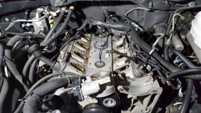
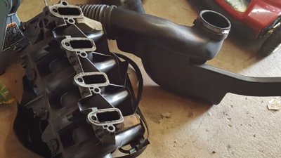
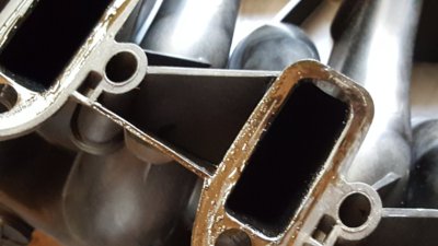
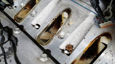
Here is the top end after 1.5 hours. Got this far using only an 8 and 10mm socket. The fuel rail to manifold hold downs required a torx bit. Notice the amount of oil in the runners. It's pretty bad. I had this all cleaned up last time I replaced the intake manifold gasket. I have the newer rocker covers so not sure what the deal is. It's sucking oil from the pcv orifice is my guess. Looks like my knock sensor rtv dam is holding up great. I've not gotten any water on the engine bay since so didn't expect any water in there anyway. This oil issue worries me a bit. Blowby from pistons or just a head issue?? Dunno. Any tips?

20180712_094407.jpg 20180712_094424.jpg 20180712_094437.jpg 20180712_094430.jpg
 

about20ninj45

Full Access Member
Joined
May 13, 2014
Posts
1,120
Reaction score
330
positive crankcase ventilation. The gases along with oil from the crankcase, gets sucked into the TB and via vacuum and ends up in the intake and runners. definitely get a catch can if you dont have one
 

Forum statistics

Threads
132,739
Posts
1,873,421
Members
97,567
Latest member
a9lyphe
Top