Disclaimer: Links on this page pointing to Amazon, eBay and other sites may include affiliate code. If you click them and make a purchase, we may earn a small commission.

OP
OP
S

stretchit

Member
Joined
May 11, 2023
Posts
33
Reaction score
18
Another update....... all previously crimped wires have been individually soldered. Even moved a back ground thinking it might help lol.
LITTERALLY NOTHING HAS CHANGED. guess it's time to take engine out and replace harness? Who knows at this point. Might look for a donor car to put engine in. F U, GM. Garbage electrical issues. Stupid. Im mad
 

Doubeleive

Wes
Supporting Member
Joined
Nov 7, 2017
Posts
26,193
Reaction score
39,253
Location
Stockton, Ca.
Another update....... all previously crimped wires have been individually soldered. Even moved a back ground thinking it might help lol.
LITTERALLY NOTHING HAS CHANGED. guess it's time to take engine out and replace harness? Who knows at this point. Might look for a donor car to put engine in. F U, GM. Garbage electrical issues. Stupid. Im mad
something doesn't make sense, you tested each wire for ohm's/ground/voltage?
tested each pin between the pcm and throttle body?
 
OP
OP
S

stretchit

Member
Joined
May 11, 2023
Posts
33
Reaction score
18
something doesn't make sense, you tested each wire for ohm's/ground/voltage?
tested each pin between the pcm and throttle body?
No just visual inspections. Did some research and am now going to check each wire Individually, ohms, voltage, and whatever else. Thanks for the help, I will keep posting updates. Hopefully I can pin point it!
 
OP
OP
S

stretchit

Member
Joined
May 11, 2023
Posts
33
Reaction score
18
The cable from the pedal sensor to the TAC module has a continuous electrical path. Same for the cable from the TAC module (right side) all the way to the TPS connection. Going to check the other 8 wires coming from that TAC module cable to the fuse box.
 
OP
OP
S

stretchit

Member
Joined
May 11, 2023
Posts
33
Reaction score
18
The cable from the pedal sensor to the TAC module has a continuous electrical path. Same for the cable from the TAC module (right side) all the way to the TPS connection. Going to check the other 8 wires coming from that TAC module cable to the fuse box.
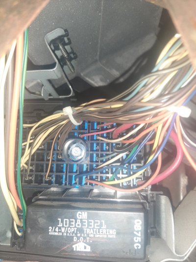
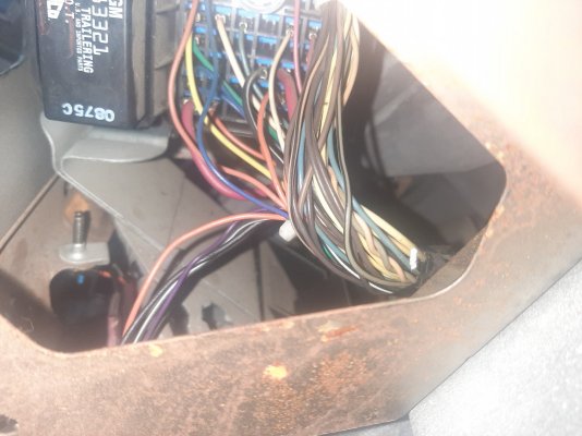
Just finished checking and I have flow all the way thru to the fuse block. Noticed a little dirt in the fuse box right where the cables connect. Just going to clean it real good and put everything back. If that doesn't change anything I will move on to checking grounds for continuous flow. After that I'll plug the battery back in and check voltage. Then idk lol
 
OP
OP
S

stretchit

Member
Joined
May 11, 2023
Posts
33
Reaction score
18
Also this is what my OBD port looks like. Thought this truck had a CAN network but im not sure. That's the first thing I wanted to test. Based off the port, I can't test it thru there.
20240503_194251.jpg
 
OP
OP
S

stretchit

Member
Joined
May 11, 2023
Posts
33
Reaction score
18
follow the harness for the obd port back and see what's up there should be more than 3 wires
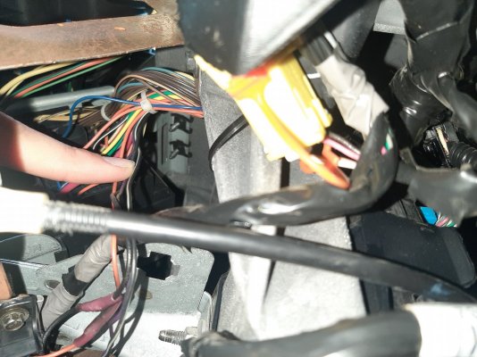
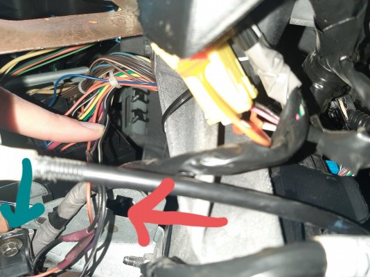
It has four wires that I followed and they just tie into the harness then connect I to the driver side fuse box. I guess I should test continuity? Or keep digging. Seems like it should have more then 4 pins/wires in the OBD port

*Red arrow is the 4 wires from the OBD port
*Green arrow is the OBD port

*forgot to mention that the previous owner had a tracker that was spliced Into the ground and voltage wire of the OBD. Took that out but the throttle response issue didn't change
 

Attachments

  • 20240521_125547.jpg
    20240521_125547.jpg
    316.6 KB · Views: 9
  • 20240521_125518.jpg
    20240521_125518.jpg
    244.6 KB · Views: 8
  • 20240521_124040.jpg
    20240521_124040.jpg
    313.6 KB · Views: 9
  • 20240521_124040.jpg
    20240521_124040.jpg
    307.3 KB · Views: 6
Last edited:

Doubeleive

Wes
Supporting Member
Joined
Nov 7, 2017
Posts
26,193
Reaction score
39,253
Location
Stockton, Ca.
you seem to be missing pins 6 & 14 which is can bus high & low, has this thing had a engine swap or anything?
 
OP
OP
S

stretchit

Member
Joined
May 11, 2023
Posts
33
Reaction score
18
you seem to be missing pins 6 & 14 which is can bus high & low, has this thing had a engine swap or anything?
No not too my knowledge. Its a 5.3 LM7. When I took it apart it looked pretty dirty and stock.

Thanks for letting me know, I felt like I should have those to test it. Not sure what to do now lol thanks again for the help
 

Forum statistics

Threads
132,295
Posts
1,865,508
Members
96,878
Latest member
Jman2
Top